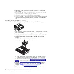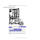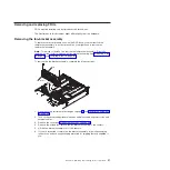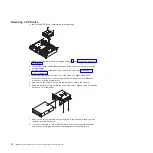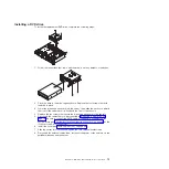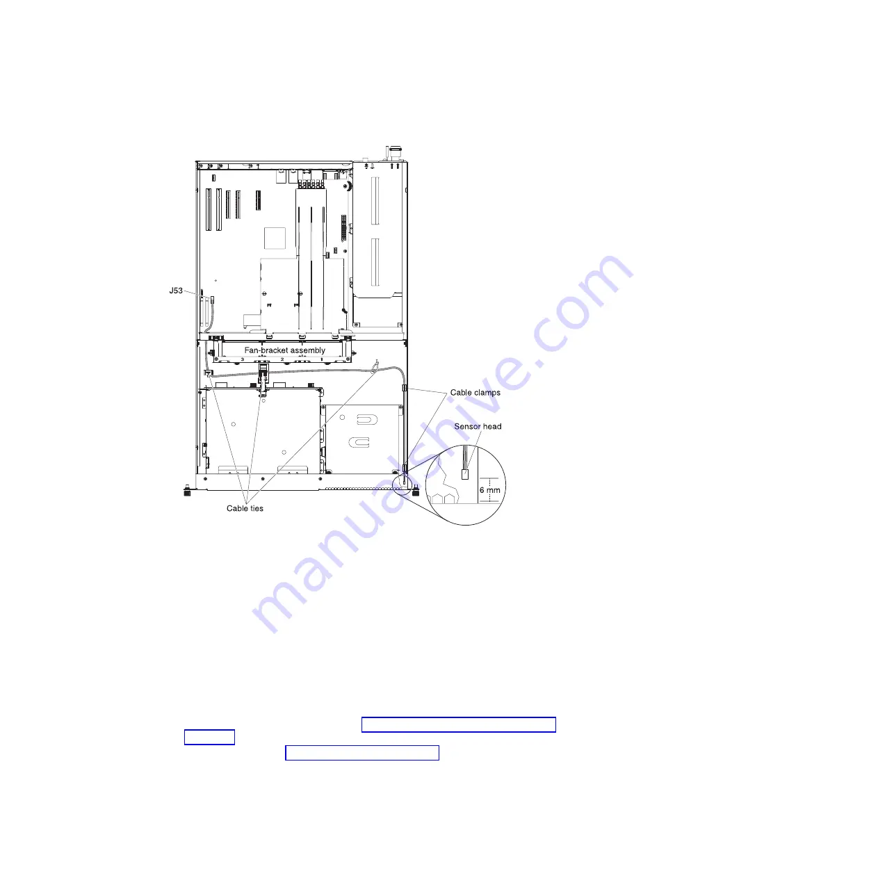
Installing the thermal-sensor cable
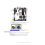
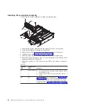
To install the thermal-sensor cable, complete the following steps:
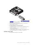
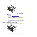
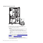
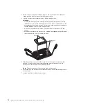
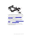
1. Orient the cable so that the sensor head is toward the front of the server.
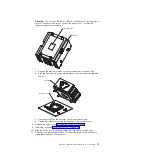
2. Route the cable as shown in the illustration.
Important:
a. Thread the cable toward the front of the chassis, sensor head first, through
the two cable clips on the right side of the server chassis.
b. Make sure that the sensor head of the cable stops approximately 6 mm
(0.25 inches) from the front of the chassis and
does not touch the front of
the chassis
.
c. Use the cable ties in front of the fan-bracket assembly to secure the thermal
cable.
d. Thread the connector end of the cable through the opening in the fan wall.
3. Connect the cable to the thermal-cable connector (J53, near the SAS channel B
connector) on the system board. See “System-board internal cable connectors”
on page 9 for the connector location.
4. Install the cover (see “Installing the cover” on page 46).
5. Slide the server into the rack and tighten the rack release thumbscrews.
6. Reconnect the external cables; then, reconnect the power cords and turn on the
peripheral devices and the server.
66
IBM System x3610 Type 7942: Problem Determination and Service Guide
Summary of Contents for System x3610
Page 1: ...IBM System x3610 Type 7942 Problem Determination and Service Guide...
Page 2: ......
Page 3: ...IBM System x3610 Type 7942 Problem Determination and Service Guide...
Page 8: ...vi IBM System x3610 Type 7942 Problem Determination and Service Guide...
Page 32: ...14 IBM System x3610 Type 7942 Problem Determination and Service Guide...
Page 54: ...36 IBM System x3610 Type 7942 Problem Determination and Service Guide...
Page 143: ......
Page 144: ...Part Number 49Y0084 Printed in USA 1P P N 49Y0084...

