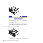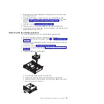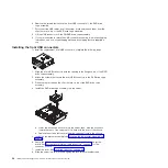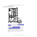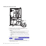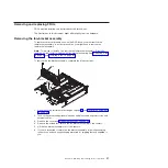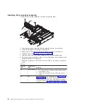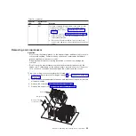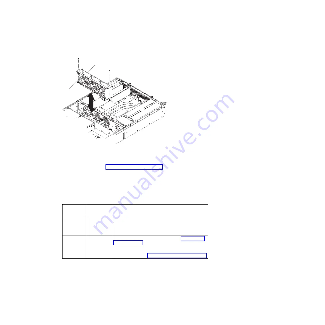
Installing the fan-bracket assembly
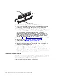
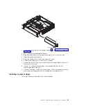
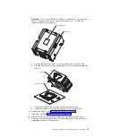
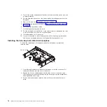
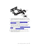
To install the fan-bracket assembly, complete the following steps.
Fan bracket
Fan
1. Align the fan-bracket assembly with the assembly location on the chassis.
2. Lower the fan-bracket assembly into the chassis.
3. Replace the screws that secure the fan-bracket assembly to the chassis.
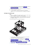
4. Install the cover (see “Installing the cover” on page 46).
5. Slide the server into the rack and tighten the rack release thumbscrews.
6. Reconnect the external cables; then, reconnect the power cords and turn on the
peripheral devices and the server.
7. Check the system-error LED and the fan error LED on the operator information
panel.
Table 10.
Fan error
LED
System-error
LED
Meaning
On
Any condition
1. The replacement fan-bracket assembly might be faulty;
install a different one.
2. (Trained service technician only) replace the system
board.
Off
On
Check the LEDs on the system board (see “System-board
LEDs” on page 12). An error LED (amber) that is lit on the
system board or an LED on the hard disk drive backplane
or system board that is off when it should be on can help
isolate the error. See Chapter 5, “Diagnostics,” on page 83.
68
IBM System x3610 Type 7942: Problem Determination and Service Guide
Summary of Contents for System x3610
Page 1: ...IBM System x3610 Type 7942 Problem Determination and Service Guide...
Page 2: ......
Page 3: ...IBM System x3610 Type 7942 Problem Determination and Service Guide...
Page 8: ...vi IBM System x3610 Type 7942 Problem Determination and Service Guide...
Page 32: ...14 IBM System x3610 Type 7942 Problem Determination and Service Guide...
Page 54: ...36 IBM System x3610 Type 7942 Problem Determination and Service Guide...
Page 143: ......
Page 144: ...Part Number 49Y0084 Printed in USA 1P P N 49Y0084...

