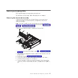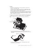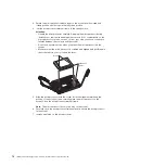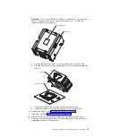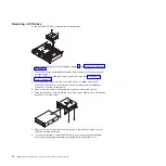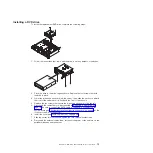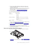
8. Remove each microprocessor heat sink and microprocessor; then, place them
on a static-protective surface for reinstallation (see “Removing a
microprocessor” on page 69).
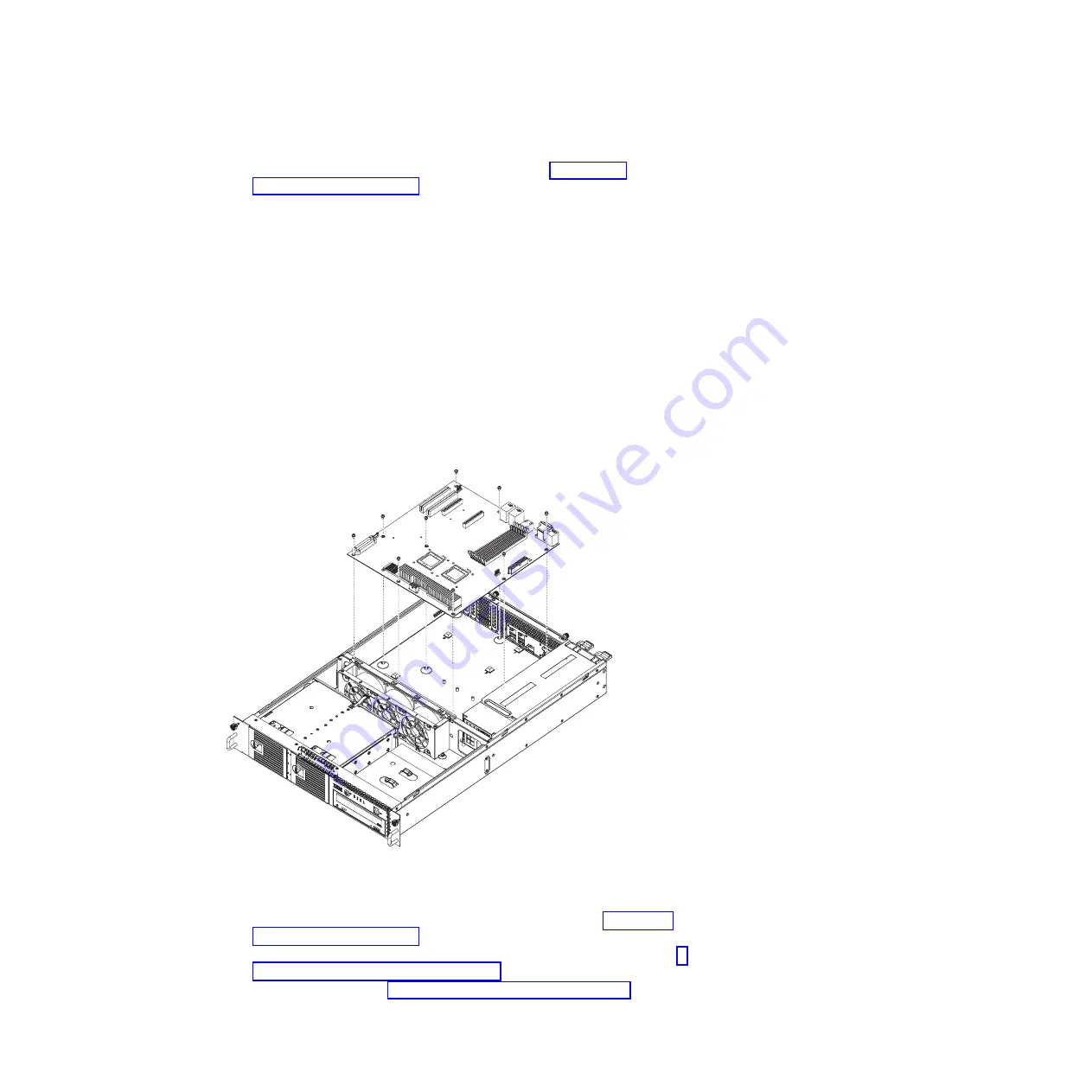
9. Remove the remaining 9 screws that secure the system board to the chassis.
10. Lift the system board out of the server.
11. If you are instructed to return the system board, follow all packaging
instructions, and use any packaging materials for shipping that are supplied to
you.
Installing the system board
Notes:
1. When you reassemble the components in the server, be sure to route all cables
carefully so that they are not exposed to excessive pressure.
2. When you replace the system board, you must either update the server with the
latest firmware or restore the pre-existing firmware that the customer provides
on a diskette or CD image.
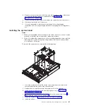
To reinstall the system board, complete the following steps.
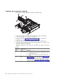
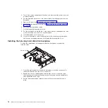
1. Lower the system board into the server; then, align the screw holes in the
system board with the holes in the chassis bottom.
2. Replace the 9 screws that secure the system board to the chassis.
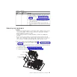
3. Install each microprocessor with its matching heat sink (see “Installing a
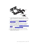
4. Reconnect to the system board the cables that you disconnected in step 7 of
“Removing the system board” on page 80.
5. Install the DIMMs (see “Installing a memory module” on page 52).
6. Install the air duct.
Chapter 4. Removing and replacing server components
81
Summary of Contents for System x3610
Page 1: ...IBM System x3610 Type 7942 Problem Determination and Service Guide...
Page 2: ......
Page 3: ...IBM System x3610 Type 7942 Problem Determination and Service Guide...
Page 8: ...vi IBM System x3610 Type 7942 Problem Determination and Service Guide...
Page 32: ...14 IBM System x3610 Type 7942 Problem Determination and Service Guide...
Page 54: ...36 IBM System x3610 Type 7942 Problem Determination and Service Guide...
Page 143: ......
Page 144: ...Part Number 49Y0084 Printed in USA 1P P N 49Y0084...

