4.
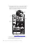
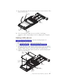
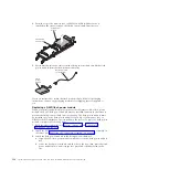
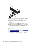
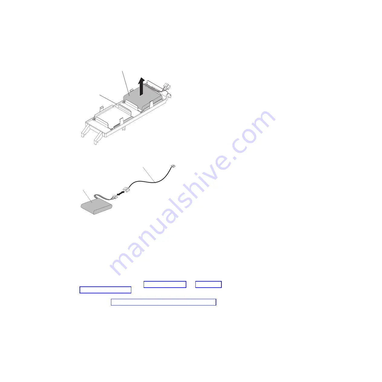
From the top of the memory tray or DIMM air baffle (whichever one is
installed in the server), remove the flash power module from the tray.
Flash power
module tray
Flash power
module
5.
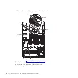
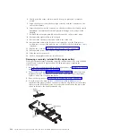
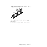
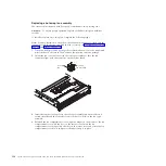
Disconnect the extension cable from the flash power module and lift the flash
power module from the flash power module tray.
Flash
power
module
Extension cable
(not required)
If you are instructed to return the flash power module, follow all packaging
instructions, and use any packaging materials for shipping that are supplied to
you.
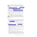
Replacing a RAID flash power module
When you install any RAID adapter in the server that comes with a flash power
module, the RAID flash power module must be installed remotely in the server to
prevent the flash power module from overheating. The flash power module must
be installed only in the flash power module tray on top of the memory tray or
DIMM air baffle (whichever one is installed in the server). To replace a flash power
module, complete the following steps:
1.
Read the safety information in “Safety” on page vii and “Installation
guidelines” on page 261.
2.
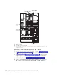
Install the RAID adapter on the riser-card and install the riser-card assembly in
the server (see “Replacing a PCI riser-card assembly” on page 337).
3.
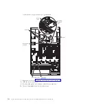
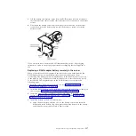
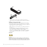
Install the flash power module in the flash power module tray:
a.
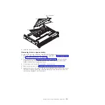
Align the new flash power module with the slot on the flash power module
tray.
b.
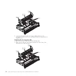
Lower the flash power module onto the slot in the tray; then, press the flash
power module down until it snaps into place and is firmly seated in the
slot.
320
System x3690 X5 Types 7147, 7148, 7149, and 7192: Problem Determination and Service Guide
Summary of Contents for System x3690 X5
Page 1: ...System x3690 X5 Types 7147 7148 7149 and 7192 Problem Determination and Service Guide...
Page 2: ......
Page 3: ...System x3690 X5 Types 7147 7148 7149 and 7192 Problem Determination and Service Guide...
Page 8: ...vi System x3690 X5 Types 7147 7148 7149 and 7192 Problem Determination and Service Guide...
Page 13: ...Safety statements Safety xi...
Page 22: ...4 System x3690 X5 Types 7147 7148 7149 and 7192 Problem Determination and Service Guide...
Page 266: ...248 System x3690 X5 Types 7147 7148 7149 and 7192 Problem Determination and Service Guide...
Page 278: ...260 System x3690 X5 Types 7147 7148 7149 and 7192 Problem Determination and Service Guide...
Page 386: ...368 System x3690 X5 Types 7147 7148 7149 and 7192 Problem Determination and Service Guide...
Page 407: ...1 2 Chapter 5 Removing and replacing components 389...
Page 444: ...426 System x3690 X5 Types 7147 7148 7149 and 7192 Problem Determination and Service Guide...
Page 454: ...436 System x3690 X5 Types 7147 7148 7149 and 7192 Problem Determination and Service Guide...
Page 461: ...weight of memory enclosure 28 Index 443...
Page 462: ...444 System x3690 X5 Types 7147 7148 7149 and 7192 Problem Determination and Service Guide...
Page 463: ......
Page 464: ...Part Number 47C8865 Printed in USA 1P P N 47C8865...

