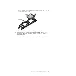
Note:
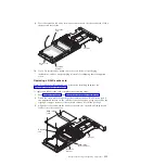
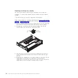
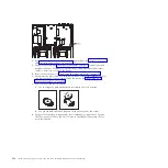
The flash power module does not require a retention clip to hold the
flash power module in place.
Flash power
module tray
Flash power
module
c.
Reconnect the extension cable to the flash power module.
4.
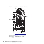
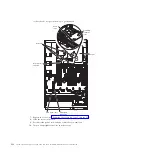
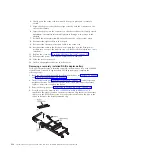
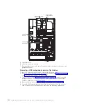
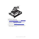
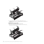
Ensure that the flash power module cable is routed in the server as shown in
the following illustrations (depending on the PCI slot in which the RAID
adapter is installed).
Attention:
Make sure that the cable is not pinched and does not cover any
connectors or obstruct any components on the system board.
Chapter 5. Removing and replacing components
321
Summary of Contents for System x3690 X5
Page 1: ...System x3690 X5 Types 7147 7148 7149 and 7192 Problem Determination and Service Guide...
Page 2: ......
Page 3: ...System x3690 X5 Types 7147 7148 7149 and 7192 Problem Determination and Service Guide...
Page 8: ...vi System x3690 X5 Types 7147 7148 7149 and 7192 Problem Determination and Service Guide...
Page 13: ...Safety statements Safety xi...
Page 22: ...4 System x3690 X5 Types 7147 7148 7149 and 7192 Problem Determination and Service Guide...
Page 266: ...248 System x3690 X5 Types 7147 7148 7149 and 7192 Problem Determination and Service Guide...
Page 278: ...260 System x3690 X5 Types 7147 7148 7149 and 7192 Problem Determination and Service Guide...
Page 386: ...368 System x3690 X5 Types 7147 7148 7149 and 7192 Problem Determination and Service Guide...
Page 407: ...1 2 Chapter 5 Removing and replacing components 389...
Page 444: ...426 System x3690 X5 Types 7147 7148 7149 and 7192 Problem Determination and Service Guide...
Page 454: ...436 System x3690 X5 Types 7147 7148 7149 and 7192 Problem Determination and Service Guide...
Page 461: ...weight of memory enclosure 28 Index 443...
Page 462: ...444 System x3690 X5 Types 7147 7148 7149 and 7192 Problem Determination and Service Guide...
Page 463: ......
Page 464: ...Part Number 47C8865 Printed in USA 1P P N 47C8865...


