Flashing rapidly (4 times per second):
The server is turned off and is not
ready to be turned on. The power-control button is disabled. This lasts
approximately 1 to 3 minutes.
Flashing slowly (once per second):
The server is turned off and is ready to
be turned on. You can press the power-control button to turn on the server.
Lit:
The server is turned on.
Fading on and off:
The server is in a reduced-power state. To wake the
server, press the power-control button or use the IMM Web interface. See
“Logging on to the Web interface” on page 413 for information about logging
on to the IMM Web interface.
v
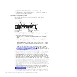
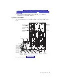
Locator LED:
Use this LED to visually locate the server among other servers.
You can use IBM Systems Director to light this LED remotely. This LED is
functionally equivalent to the locator LED on the front of the server.
v
Video connector:
Connect a monitor to this connector. The video connectors on
the front and rear of the server can be used simultaneously.
Note:
The maximum video resolution is 1280 x 1024 at 75 Hz.
v
Serial connector:
Connect a 9-pin serial device to this connector. The serial port
is shared with the integrated management module (IMM). The IMM can take
control of the shared serial port to perform text console redirection and to
redirect serial traffic, using Serial over LAN (SOL).
v
USB connectors:
Connect a USB device, such as a USB mouse, keyboard, or
other device to any of these connectors.
v
Systems-management Ethernet connector:
Use this connector to connect the
server to a network for full systems-management information control.
v
QPI link LEDs
When these LEDs are lit, they indicate that there is an active link connection to
the MAX5 or another x3690 server.
v
Ethernet activity LEDs:
When these LEDs are lit, they indicate that the server is
transmitting to or receiving signals from the Ethernet LAN that is connected to
the Ethernet port.
v
Ethernet link LEDs:
When these LEDs are lit, they indicate that there is an
active link connection on the 10BASE-T, 100BASE-TX, or 1000BASE-TX interface
for the Ethernet port.
v
Ethernet connectors:
Use either of these connectors to connect the server to a
network. When you use the Ethernet 1 connector, the network can be shared
with the IMM through a single network cable.
16
System x3690 X5 Types 7147, 7148, 7149, and 7192: Problem Determination and Service Guide
Summary of Contents for System x3690 X5
Page 1: ...System x3690 X5 Types 7147 7148 7149 and 7192 Problem Determination and Service Guide...
Page 2: ......
Page 3: ...System x3690 X5 Types 7147 7148 7149 and 7192 Problem Determination and Service Guide...
Page 8: ...vi System x3690 X5 Types 7147 7148 7149 and 7192 Problem Determination and Service Guide...
Page 13: ...Safety statements Safety xi...
Page 22: ...4 System x3690 X5 Types 7147 7148 7149 and 7192 Problem Determination and Service Guide...
Page 266: ...248 System x3690 X5 Types 7147 7148 7149 and 7192 Problem Determination and Service Guide...
Page 278: ...260 System x3690 X5 Types 7147 7148 7149 and 7192 Problem Determination and Service Guide...
Page 386: ...368 System x3690 X5 Types 7147 7148 7149 and 7192 Problem Determination and Service Guide...
Page 407: ...1 2 Chapter 5 Removing and replacing components 389...
Page 444: ...426 System x3690 X5 Types 7147 7148 7149 and 7192 Problem Determination and Service Guide...
Page 454: ...436 System x3690 X5 Types 7147 7148 7149 and 7192 Problem Determination and Service Guide...
Page 461: ...weight of memory enclosure 28 Index 443...
Page 462: ...444 System x3690 X5 Types 7147 7148 7149 and 7192 Problem Determination and Service Guide...
Page 463: ......
Page 464: ...Part Number 47C8865 Printed in USA 1P P N 47C8865...


