v
The microprocessor options that IBM supports are limited by the capacity and
capability of the server. Any microprocessor options that you install must have
the same specifications as the microprocessor(s) that came with the server.
v
The first microprocessor must always be installed in microprocessor socket 1 on
the system board.
v
When one microprocessor is installed, a heat sink filler is not required for
microprocessor socket 2, however, the microprocessor air baffle, the DIMM air
baffle, and the memory tray must be installed to provide proper system cooling.
v
Do not remove the first microprocessor from the system board when you install
the second microprocessor.
v
When you install the second microprocessor, you must also install additional
memory. See “Replacing a memory module” on page 296 for details about the
installation sequence.
v
To ensure proper server operation when you install an additional
microprocessor, use microprocessors that have the same QuickPath Interconnect
(QPI) link speed, integrated memory controller frequency, core frequency, power
segment, internal cache size, and type.
v
Mixing microprocessors of different stepping levels within the same server
model is supported.
v
When mixing microprocessors with different stepping levels within the same
server model, you do not have to install the microprocessor with lowest
stepping level and features in microprocessor socket 1.
v
Both microprocessor voltage regulator modules are integrated on the system
board.
v
If you have to replace a microprocessor, call for service.
v
Read the documentation that comes with the microprocessor, so that you can
determine whether you have to update the UEFI firmware. To download the
most current level of server firmware, go to http://www.ibm.com/support/
fixcentral/systemx/groupView?query.productGroup=ibm%2FSystemx/.
Important:
Some cluster solutions require specific code levels or coordinated
code updates. If the device is part of a cluster solution, verify that the latest level
of code is supported for the cluster solution before you update the code.
v
The microprocessor speeds are automatically set for this server; therefore, you
do not have to set any microprocessor frequency-selection jumpers or switches.
v
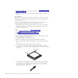
If the thermal-grease protective cover (for example, a plastic cap or tape liner) is
removed from the heat sink, do not touch the thermal grease on the bottom of
the heat sink or set down the heat sink. For more information about applying or
working with thermal grease, see “Thermal grease” on page 356.
Note:
Removing the heat sink from the microprocessor destroys the even
distribution of the thermal grease and requires replacing the thermal grease.
v
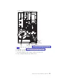
The following table shows the DIMM connectors on the system board and the
memory tray that are associated with each microprocessor:
Table 23. DIMM connectors associated with each microprocessor
Microprocessor
DIMM connectors
Microprocessor socket 1
1 through 16
Microprocessor socket 2
17 through 32
Note:
When the memory tray is not installed in the server, DIMMs 1 through 16
are solely associated with microprocessor 1. Microprocessor 2 has access to
352
System x3690 X5 Types 7147, 7148, 7149, and 7192: Problem Determination and Service Guide
Summary of Contents for System x3690 X5
Page 1: ...System x3690 X5 Types 7147 7148 7149 and 7192 Problem Determination and Service Guide...
Page 2: ......
Page 3: ...System x3690 X5 Types 7147 7148 7149 and 7192 Problem Determination and Service Guide...
Page 8: ...vi System x3690 X5 Types 7147 7148 7149 and 7192 Problem Determination and Service Guide...
Page 13: ...Safety statements Safety xi...
Page 22: ...4 System x3690 X5 Types 7147 7148 7149 and 7192 Problem Determination and Service Guide...
Page 266: ...248 System x3690 X5 Types 7147 7148 7149 and 7192 Problem Determination and Service Guide...
Page 278: ...260 System x3690 X5 Types 7147 7148 7149 and 7192 Problem Determination and Service Guide...
Page 386: ...368 System x3690 X5 Types 7147 7148 7149 and 7192 Problem Determination and Service Guide...
Page 407: ...1 2 Chapter 5 Removing and replacing components 389...
Page 444: ...426 System x3690 X5 Types 7147 7148 7149 and 7192 Problem Determination and Service Guide...
Page 454: ...436 System x3690 X5 Types 7147 7148 7149 and 7192 Problem Determination and Service Guide...
Page 461: ...weight of memory enclosure 28 Index 443...
Page 462: ...444 System x3690 X5 Types 7147 7148 7149 and 7192 Problem Determination and Service Guide...
Page 463: ......
Page 464: ...Part Number 47C8865 Printed in USA 1P P N 47C8865...

