DIMMs 1 through 16, but access is through microprocessor 1. This is important
if load balancing is a necessity for your operating system or software load.
To install an additional microprocessor and heat sink, complete the following steps:
Attention:
When you handle static-sensitive devices, take precautions to avoid
damage from static electricity. For details about handling these devices, see
“Handling static-sensitive devices” on page 263.
1.
Read the safety information that begins on page “Safety” on page vii and
“Installation guidelines” on page 261.
2.
Install the microprocessor:
a.
Remove the static-protective bag, and the foam surrounding the bag, from
the box.
b.
Touch the static-protective package that contains the new microprocessor to
any
unpainted
metal surface on the server; then, remove the microprocessor
from the package.
Attention:
v
Do not touch the microprocessor contacts; handle the microprocessor by
the edges only. Contaminants on the microprocessor contacts, such as oil
from your skin, can cause connection failures between the contacts and
the socket.
v
Handle the microprocessor carefully. Dropping the microprocessor during
installation or removal can damage the contacts.
v
Do not use excessive force when you press the microprocessor into the
socket.
v
Make sure that the microprocessor is oriented and aligned and positioned
in the socket before you try to close the lever.
c.
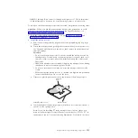
If there is a plastic protective cover on the bottom of the microprocessor,
carefully remove it.
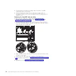
Microprocessor
Protective
cover
d.
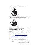
Twist the handle of the microprocessor installation tool counterclockwise so
that it is in the open position.
Note:
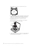
If you are installing E7 series microprocessors in your server, you
must use the microprocessor installation tool with the text “X7500 + E7” on
the bottom of the tool (see the following illustration). Tools that do not have
Chapter 5. Removing and replacing components
353
Summary of Contents for System x3690 X5
Page 1: ...System x3690 X5 Types 7147 7148 7149 and 7192 Problem Determination and Service Guide...
Page 2: ......
Page 3: ...System x3690 X5 Types 7147 7148 7149 and 7192 Problem Determination and Service Guide...
Page 8: ...vi System x3690 X5 Types 7147 7148 7149 and 7192 Problem Determination and Service Guide...
Page 13: ...Safety statements Safety xi...
Page 22: ...4 System x3690 X5 Types 7147 7148 7149 and 7192 Problem Determination and Service Guide...
Page 266: ...248 System x3690 X5 Types 7147 7148 7149 and 7192 Problem Determination and Service Guide...
Page 278: ...260 System x3690 X5 Types 7147 7148 7149 and 7192 Problem Determination and Service Guide...
Page 386: ...368 System x3690 X5 Types 7147 7148 7149 and 7192 Problem Determination and Service Guide...
Page 407: ...1 2 Chapter 5 Removing and replacing components 389...
Page 444: ...426 System x3690 X5 Types 7147 7148 7149 and 7192 Problem Determination and Service Guide...
Page 454: ...436 System x3690 X5 Types 7147 7148 7149 and 7192 Problem Determination and Service Guide...
Page 461: ...weight of memory enclosure 28 Index 443...
Page 462: ...444 System x3690 X5 Types 7147 7148 7149 and 7192 Problem Determination and Service Guide...
Page 463: ......
Page 464: ...Part Number 47C8865 Printed in USA 1P P N 47C8865...


