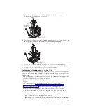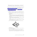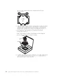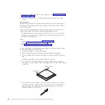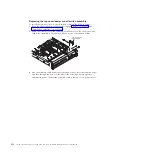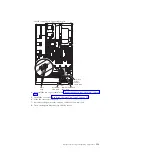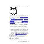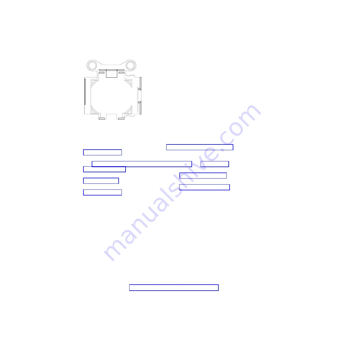
bottom of the tool (see the following illustration). Tools that do not have this
text on the bottom will not work correctly with the E7 series microprocessors.
X7500
+
E7
10.
Install the socket covers that you removed from the microprocessor sockets on
the new system board and place them on the microprocessor sockets of the
old system board, if you have not done so.
11.
Reconnect the cables that you disconnected earlier to the system board.
12.
Reinstall the microprocessor air baffle (see “Replacing the microprocessor air
baffle” on page 269).
13.
Reinstall the PCI riser-card assemblies with the adapters, if any were installed
(see “Replacing a PCI riser-card assembly” on page 337 and “Replacing an
adapter” on page 275).
14.
Reinstall the memory tray, if you removed it (see “Replacing the memory
tray” on page 267).
15.
Reinstall DIMM air baffle, if you removed it (see “Replacing the DIMM air
baffle” on page 271).
16.
Reconnect the remote RAID battery cables to the adapters and install the
RAID battery trays in memory tray or DIMM air baffle, if you removed it
earlier.
17.
Install the QPI fillers or QPI cables that you removed from the old system
board onto the QPI ports on the new system board, if you removed them
earlier.
Attention:
v
When you handle the QPI cables, take precautions to avoid damaging the
high density interface. Dropping and incorrectly connecting the QPI cables
can damage the high density interface. Store the protective covers that come
on the end of the QPI cables for reuse when you perform maintenance on
the server or when you remove the cables for some reason.
v
If the server is connected to a MAX5 memory expansion modules (one 3U
configurations), see the documentation for the QPI cabling option kit for
other important cabling information when disconnecting or connecting QPI
cables.
18.
Reinstall the cover (see “Replacing the server top cover” on page 265).
19.
Slide the server into the rack.
20.
Reconnect the power cords and any cables that you removed.
21.
Turn on the peripheral devices and the server.
Important:
Perform the following updates:
v
Either update the server with the latest RAID firmware or restore the
pre-existing firmware from a diskette or CD image.
Chapter 5. Removing and replacing components
365
Summary of Contents for System x3690 X5
Page 1: ...System x3690 X5 Types 7147 7148 7149 and 7192 Problem Determination and Service Guide...
Page 2: ......
Page 3: ...System x3690 X5 Types 7147 7148 7149 and 7192 Problem Determination and Service Guide...
Page 8: ...vi System x3690 X5 Types 7147 7148 7149 and 7192 Problem Determination and Service Guide...
Page 13: ...Safety statements Safety xi...
Page 22: ...4 System x3690 X5 Types 7147 7148 7149 and 7192 Problem Determination and Service Guide...
Page 266: ...248 System x3690 X5 Types 7147 7148 7149 and 7192 Problem Determination and Service Guide...
Page 278: ...260 System x3690 X5 Types 7147 7148 7149 and 7192 Problem Determination and Service Guide...
Page 386: ...368 System x3690 X5 Types 7147 7148 7149 and 7192 Problem Determination and Service Guide...
Page 407: ...1 2 Chapter 5 Removing and replacing components 389...
Page 444: ...426 System x3690 X5 Types 7147 7148 7149 and 7192 Problem Determination and Service Guide...
Page 454: ...436 System x3690 X5 Types 7147 7148 7149 and 7192 Problem Determination and Service Guide...
Page 461: ...weight of memory enclosure 28 Index 443...
Page 462: ...444 System x3690 X5 Types 7147 7148 7149 and 7192 Problem Determination and Service Guide...
Page 463: ......
Page 464: ...Part Number 47C8865 Printed in USA 1P P N 47C8865...

