(DIMMs with DRAMs that are organized with 4 data lanes) and x8 technology
(DIMMs with DRAMs that are organized with 8 data lanes) in the same memory
port. The following table shows the DIMM connectors on the eight memory
ports.
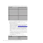
Table 24. DIMM connectors on each memory port
Memory ports
DIMM connectors
1
1, 2, 7, and 8
2
3, 4, 5, and 6
3
9, 10, 15, and 16
4
11, 12, 13, and 14
5
17, 18, 23, and 24
6
19, 20, 21, and 22
7
25, 26, 31, and 32
8
27, 28, 29, and 30
Note:
2 GB, 4 GB, and 8 GB DIMMs are x4 technology DIMMs. 16 GB and 32 GB DIMMs
are x8 technology DIMMs.
v
Do not mix DIMMs with 1 Gb (gigabit) DRAM technology, 2 Gb DRAM
technology, or other gigabit DRAM technologies in banks of eight DIMMs on
memory ports (memory channels) that are on the same memory controller. This
is not supported on the MAX5. The following table lists the DIMM connectors
for each bank of eight DIMMs that are on the memory ports within the same
memory controller.
Table 25. DIMM connectors on memory ports within the same memory controller
Bank of DIMMs
DIMM connectors
1st bank of DIMMs
1, 2, 3, 4, 5, 6, 7, and 8
2nd bank of DIMMs
9, 10, 11, 12, 13, 14, 15, and 16
3rd bank of DIMMs
17, 18, 19, 20, 21, 22, 23, and 24
4th bank of DIMMs
25, 26, 27, 28, 29, 30, 31, and 32
v
DIMMs must be installed in pairs for non-mirroring mode and in sets of four for
memory-mirroring.
v
A minimum of two DIMMs must be installed in the MAX5 for each
microprocessor in the host server.
v
The maximum operating speed of the MAX5 is determined by the slowest
DIMM installed in the MAX5.
v
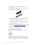
The MAX5 does not come with any DIMMs installed when you purchase it as a
option. When you install DIMMs, install them in the order shown in the
following tables to optimize system performance.
v
The MAX5 supports non-mirroring mode and memory-mirroring mode through
the host server.
–
Non-mirroring mode
. When you use the non-mirroring mode, install DIMMs
as indicated in the following table:
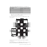
Table 26. Non-mirroring mode DIMM population sequence for the MAX5 memory expansion
module
Pairs of DIMMs
DIMM connector population sequence
Pair 1
28, 29
Chapter 5. Removing and replacing components
385
Summary of Contents for System x3690 X5
Page 1: ...System x3690 X5 Types 7147 7148 7149 and 7192 Problem Determination and Service Guide...
Page 2: ......
Page 3: ...System x3690 X5 Types 7147 7148 7149 and 7192 Problem Determination and Service Guide...
Page 8: ...vi System x3690 X5 Types 7147 7148 7149 and 7192 Problem Determination and Service Guide...
Page 13: ...Safety statements Safety xi...
Page 22: ...4 System x3690 X5 Types 7147 7148 7149 and 7192 Problem Determination and Service Guide...
Page 266: ...248 System x3690 X5 Types 7147 7148 7149 and 7192 Problem Determination and Service Guide...
Page 278: ...260 System x3690 X5 Types 7147 7148 7149 and 7192 Problem Determination and Service Guide...
Page 386: ...368 System x3690 X5 Types 7147 7148 7149 and 7192 Problem Determination and Service Guide...
Page 407: ...1 2 Chapter 5 Removing and replacing components 389...
Page 444: ...426 System x3690 X5 Types 7147 7148 7149 and 7192 Problem Determination and Service Guide...
Page 454: ...436 System x3690 X5 Types 7147 7148 7149 and 7192 Problem Determination and Service Guide...
Page 461: ...weight of memory enclosure 28 Index 443...
Page 462: ...444 System x3690 X5 Types 7147 7148 7149 and 7192 Problem Determination and Service Guide...
Page 463: ......
Page 464: ...Part Number 47C8865 Printed in USA 1P P N 47C8865...


