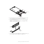
1.
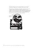
Touch the static-protective package that contains the new DIMM to any
unpainted metal surface on the outside of the MAX5; then, remove the DIMM
from the package.
2.
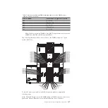
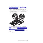
Turn the DIMM so that the DIMM keys align correctly with the connector.
3.
Insert the DIMM into the connector by aligning the edges of the DIMM with
the slots at the ends of the DIMM connector.
4.
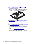
Firmly press the DIMM straight down into the connector by applying pressure
on both ends of the DIMM simultaneously. The retaining clips snap into the
locked position when the DIMM is firmly seated in the connector.
Note:
If there is a gap between the DIMM and the retaining clips, the DIMM
has not been correctly inserted; open the retaining clips, remove the DIMM,
and then reinsert it.
5.
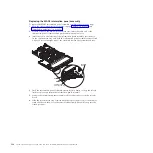
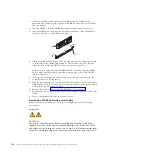
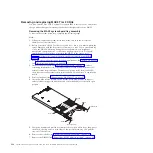
Grasp the system-board tray on both sides (near the stop-tabs) and align the
system-board tray with the chassis.
6.
Slide the system-board tray forward until the tabs at the bottom of the handles
touch the chassis; then, close the handles and press firmly on the release latches
to snap them into the locked position.
7.
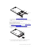
Reinstall the bezel (see “Replacing the MAX5 bezel” on page 376).
8.
Reconnect the power cords to the MAX5; then, connect all external cables to the
MAX5
9.
Turn on the peripheral devices and the host server.
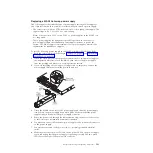
Removing a MAX5 hot-swap power supply
When you remove or install a hot-swap power supply, observe the following
precautions.
Statement 5
CAUTION:
The power control button on the device and the power switch on the power
supply do not turn off the electrical current supplied to the device. The device
also might have more than one power cord. To remove all electrical current from
the device, ensure that all power cords are disconnected from the power source.
388
System x3690 X5 Types 7147, 7148, 7149, and 7192: Problem Determination and Service Guide
Summary of Contents for System x3690 X5
Page 1: ...System x3690 X5 Types 7147 7148 7149 and 7192 Problem Determination and Service Guide...
Page 2: ......
Page 3: ...System x3690 X5 Types 7147 7148 7149 and 7192 Problem Determination and Service Guide...
Page 8: ...vi System x3690 X5 Types 7147 7148 7149 and 7192 Problem Determination and Service Guide...
Page 13: ...Safety statements Safety xi...
Page 22: ...4 System x3690 X5 Types 7147 7148 7149 and 7192 Problem Determination and Service Guide...
Page 266: ...248 System x3690 X5 Types 7147 7148 7149 and 7192 Problem Determination and Service Guide...
Page 278: ...260 System x3690 X5 Types 7147 7148 7149 and 7192 Problem Determination and Service Guide...
Page 386: ...368 System x3690 X5 Types 7147 7148 7149 and 7192 Problem Determination and Service Guide...
Page 407: ...1 2 Chapter 5 Removing and replacing components 389...
Page 444: ...426 System x3690 X5 Types 7147 7148 7149 and 7192 Problem Determination and Service Guide...
Page 454: ...436 System x3690 X5 Types 7147 7148 7149 and 7192 Problem Determination and Service Guide...
Page 461: ...weight of memory enclosure 28 Index 443...
Page 462: ...444 System x3690 X5 Types 7147 7148 7149 and 7192 Problem Determination and Service Guide...
Page 463: ......
Page 464: ...Part Number 47C8865 Printed in USA 1P P N 47C8865...

