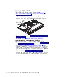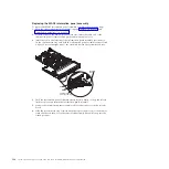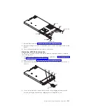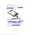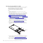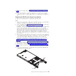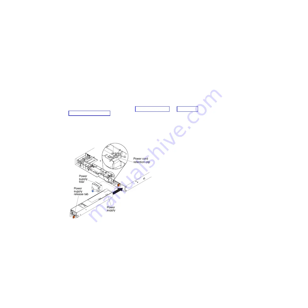
Replacing a MAX5 hot-swap power supply
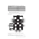
The following notes describe the type of power supply that the MAX5 supports
and other information that you must consider when you install a power supply:
v
The server comes with one 675-watt hot-swap 12-volt output power supply. The
input voltage is 110 V ac or 220 V ac auto-sensing.
Note:
You cannot mix 110 V ac and 220 V ac power supplies in the MAX5, it is
not supported.
v
These power supplies are designed for parallel operation. In the event of a
power-supply failure, the redundant power supply continues to power the
system. The MAX5 supports a maximum of two power supplies, which is the
requirement for redundancy support.
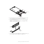
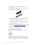
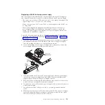
To install a hot-swap power supply in the MAX5, complete the following steps:
1.
Read the safety information that begins “Safety” on page vii and “Installation
guidelines” on page 261.
2.
Touch the static-protective package that contains the hot-swap power supply to
any unpainted metal surface on the MAX5; then, remove the power supply
from the package and place it on a static-protective surface.
3.
If you are installing a hot-swap power supply into an empty bay, remove the
power-supply filler panel from the power-supply bay.
4.
Grasp the handle on the rear of the power supply and slide the power supply
forward into the power-supply bay until it clicks. Make sure that the power
supply connects firmly into the power-supply connector.
5.
Route the power cord through the cable retention clip on the rear of the server
so that it does not accidentally become disconnected.
6.
Connect the power cord for the new power supply to the power-cord connector
on the power supply.
7.
Connect the other end of the power cord to a properly grounded electrical
outlet.
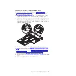
8.
Make sure that the ac power LED and the dc power LED on the power supply
are lit, indicating that the power supply is operating correctly. The two green
LEDs are to the right of the power-cord connector.
Chapter 5. Removing and replacing components
391
Summary of Contents for System x3690 X5
Page 1: ...System x3690 X5 Types 7147 7148 7149 and 7192 Problem Determination and Service Guide...
Page 2: ......
Page 3: ...System x3690 X5 Types 7147 7148 7149 and 7192 Problem Determination and Service Guide...
Page 8: ...vi System x3690 X5 Types 7147 7148 7149 and 7192 Problem Determination and Service Guide...
Page 13: ...Safety statements Safety xi...
Page 22: ...4 System x3690 X5 Types 7147 7148 7149 and 7192 Problem Determination and Service Guide...
Page 266: ...248 System x3690 X5 Types 7147 7148 7149 and 7192 Problem Determination and Service Guide...
Page 278: ...260 System x3690 X5 Types 7147 7148 7149 and 7192 Problem Determination and Service Guide...
Page 386: ...368 System x3690 X5 Types 7147 7148 7149 and 7192 Problem Determination and Service Guide...
Page 407: ...1 2 Chapter 5 Removing and replacing components 389...
Page 444: ...426 System x3690 X5 Types 7147 7148 7149 and 7192 Problem Determination and Service Guide...
Page 454: ...436 System x3690 X5 Types 7147 7148 7149 and 7192 Problem Determination and Service Guide...
Page 461: ...weight of memory enclosure 28 Index 443...
Page 462: ...444 System x3690 X5 Types 7147 7148 7149 and 7192 Problem Determination and Service Guide...
Page 463: ......
Page 464: ...Part Number 47C8865 Printed in USA 1P P N 47C8865...


