v
Follow the suggested actions in the order in which they are listed in the Action column until the problem is
solved.
v
See Chapter 4, “Parts listing, System x3690 X5 Types 7147, 7148, 7149, and 7192,” on page 249 to determine
which components are customer replaceable units (CRU) and which components are field replaceable units
(FRU).
v
If an action step is preceded by “(Trained service technician only),” that step must be performed only by a
trained service technician.
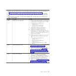
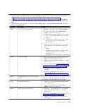
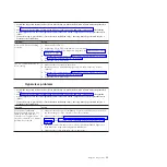
Error code
Description
Action
2011001
PCI PERR
1.
Check the riser-card LEDs.
2.
Reseat all affected adapters and riser cards.
3.
Update the PCI adapter firmware.
4.
Remove the adapter from the riser card.
5.
Replace the following components one at a time,
in the order shown, restarting the server each
time:
a.
Adapter
b.
(Trained service technician only) System board
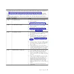
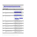
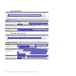
2018001
PCI Express uncorrected or uncorrected error
1.
Check the riser-card LEDs.
2.
Reseat all affected adapters and riser cards.
3.
Update the PCI adapter firmware.
4.
Remove the adapter from the riser card.
5.
Replace the following components one at a time,
in the order shown, restarting the server each
time:
a.
Adapter
b.
(Trained service technician only) System board
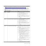
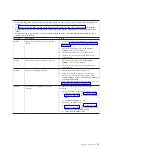
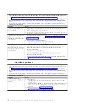
2018002
Option ROM resource allocation failure
Informational message that some devices might not
be initialized.
1.
If possible, rearrange the order of the adapters in
the PCI slots to change the load order of the
optional-device ROM code.
2.
Run the Setup utility, select
Start Options
, and
change the boot priority to change the load order
of the optional-device ROM code.
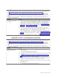
3.
Run the Setup utility and disable some other
resources, if their functions are not being used, to
make more space available.
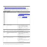
a.
Select
Start Options
, then
PXE Network
to
disable the integrated Ethernet controller
ROM.
b.
Select
Network
, then
PXE Configuration
, to
disable the ROM of the adapter in the PCI
slots.
c.
Select
Devices and I/O Ports
to disable any of
the integrated devices.
4.
Replace the following components one at a time,
in the order shown, restarting the server each
time:
a.
Each adapter
b.
(Trained service technician only) System board
Chapter 3. Diagnostics
43
Summary of Contents for System x3690 X5
Page 1: ...System x3690 X5 Types 7147 7148 7149 and 7192 Problem Determination and Service Guide...
Page 2: ......
Page 3: ...System x3690 X5 Types 7147 7148 7149 and 7192 Problem Determination and Service Guide...
Page 8: ...vi System x3690 X5 Types 7147 7148 7149 and 7192 Problem Determination and Service Guide...
Page 13: ...Safety statements Safety xi...
Page 22: ...4 System x3690 X5 Types 7147 7148 7149 and 7192 Problem Determination and Service Guide...
Page 266: ...248 System x3690 X5 Types 7147 7148 7149 and 7192 Problem Determination and Service Guide...
Page 278: ...260 System x3690 X5 Types 7147 7148 7149 and 7192 Problem Determination and Service Guide...
Page 386: ...368 System x3690 X5 Types 7147 7148 7149 and 7192 Problem Determination and Service Guide...
Page 407: ...1 2 Chapter 5 Removing and replacing components 389...
Page 444: ...426 System x3690 X5 Types 7147 7148 7149 and 7192 Problem Determination and Service Guide...
Page 454: ...436 System x3690 X5 Types 7147 7148 7149 and 7192 Problem Determination and Service Guide...
Page 461: ...weight of memory enclosure 28 Index 443...
Page 462: ...444 System x3690 X5 Types 7147 7148 7149 and 7192 Problem Determination and Service Guide...
Page 463: ......
Page 464: ...Part Number 47C8865 Printed in USA 1P P N 47C8865...

