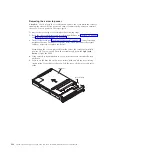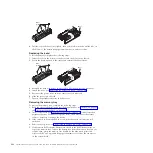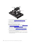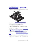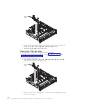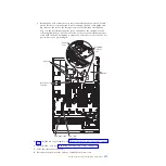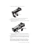
Replacing an adapter
The following notes describe the types of adapters that the server supports and
other information that you must consider when you install an adapter:
v
Locate the documentation that comes with the adapter and follow those
instructions in addition to the instructions in this section.
v
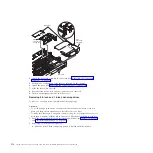
Standard models of the server comes with two PCI riser-cards installed. The
server provides up to five PCI adapter slots (depending on the PCI riser-cards
installed in the server). See “System-board optional device connectors” on page
24 for the location of the riser-card slots. The ServeRAID M1015 SAS/SATA
adapter comes installed on some standard models of the server and supports
RAID levels 0, 1, and 10. You can replace the IBM ServeRAID M1015 SAS/SATA
adapter with the optional IBM ServeRAID M5015 SAS/SATA adapter, which
provides RAID levels 0, 1, 5, 10, and 50 or the IBM ServeRAID M5016
SAS/SATA adapter, which provides RAID levels 0, 1, and 10 support. The
optional IBM ServeRAID B5015 SSD adapter and the optional IBM 6 Gb Solid
State Drive (SDD) Host Bus Adapter are also available for purchased. For
configuration information, see the documentation that comes with the adapter or
the ServeRAID documentation at http://www.ibm.com/systems/support/.
Note:
When you install an IBM ServeRAID M5015 SAS/SATA adapter or a
ServeRAID M5014 SAS/SATA adapter that has an M5000 battery in the server,
you must also use the ServeRAID M5000 Series Battery Remote Mount Cable
option to mount the battery remotely in the server.
The optional IBM ServeRAID M5016 SAS/SATA adapter comes with a
ServeRAID M5100 Series 1 GB Flash/RAID 5 Upgrade for IBM System x cache
card, which provides additional support for RAID levels 5 and 50.
In addition, the IBM 4x4 Drive Backplane ServeRAID Expansion Adapter is
available for purchase and provides additional SAS signal connectors to help
support up to six SAS cables. See Table 15 on page 276 for the PCI slot priority
installation sequence and the number of each adapter that can be installed in the
server.
Attention:
Some cluster solutions require specific code levels or coordinated
code updates. If the device is part of a cluster solution, verify that the latest level
of code is supported for the cluster solution before you update the code.
v
Do not set the maximum digital video adapter resolution above 1280 x 11024 at
75 Hz for an LCD monitor. This is the highest resolution that is supported for
any add-on video adapter that you install in the server.
v
Any high-definition video-out connector or stereo connector on any add-on
video adapter is not supported
v
The server does not support PCI-X adapters or legacy 5 V PCI adapters.
v
When you install any PCI adapter, the power cords must be disconnected from
the power source before you remove the PCI Express riser-card assembly.
Otherwise, the active power management event signal will be disabled by the
system-board logic, and the Wake on LAN feature might not work. However,
after the server is powered-on locally, the active power manager active power
management event signal will be enabled by the system-board logic.
v
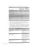
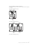
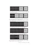
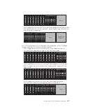
The following table provides information about the suggested PCI slot priority
sequence in which to install the adapters and how many of each adapter the
server supports. The slot priority sequence is dependent on the PCI riser cards
installed in the server and other adapters that are installed in the riser cards. See
“PCI riser card with three slots” on page 25, “PCI riser card with two slots” on
page 26, and “PCI riser card with one slot” on page 26 for the locations of the
PCI slots on the riser cards.
Chapter 5. Removing and replacing components
275
Summary of Contents for System x3690 X5
Page 1: ...System x3690 X5 Types 7147 7148 7149 and 7192 Problem Determination and Service Guide...
Page 2: ......
Page 3: ...System x3690 X5 Types 7147 7148 7149 and 7192 Problem Determination and Service Guide...
Page 8: ...vi System x3690 X5 Types 7147 7148 7149 and 7192 Problem Determination and Service Guide...
Page 13: ...Safety statements Safety xi...
Page 22: ...4 System x3690 X5 Types 7147 7148 7149 and 7192 Problem Determination and Service Guide...
Page 266: ...248 System x3690 X5 Types 7147 7148 7149 and 7192 Problem Determination and Service Guide...
Page 278: ...260 System x3690 X5 Types 7147 7148 7149 and 7192 Problem Determination and Service Guide...
Page 386: ...368 System x3690 X5 Types 7147 7148 7149 and 7192 Problem Determination and Service Guide...
Page 407: ...1 2 Chapter 5 Removing and replacing components 389...
Page 444: ...426 System x3690 X5 Types 7147 7148 7149 and 7192 Problem Determination and Service Guide...
Page 454: ...436 System x3690 X5 Types 7147 7148 7149 and 7192 Problem Determination and Service Guide...
Page 461: ...weight of memory enclosure 28 Index 443...
Page 462: ...444 System x3690 X5 Types 7147 7148 7149 and 7192 Problem Determination and Service Guide...
Page 463: ......
Page 464: ...Part Number 47C8865 Printed in USA 1P P N 47C8865...

