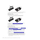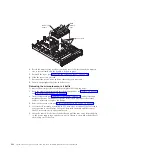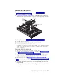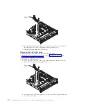
Replacing 2.5-inch and 1.8-inch hot-swap drives
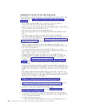
The following notes describe the type of drives that the server supports and other
information that you must consider when you install a drive. For a list of
supported drives, see http://www.ibm.com/servers/eserver/serverproven/
compat/us/.
v
Locate the documentation that comes with the drive and follow those
instructions in addition to the instructions in this chapter.
v
Make sure that you have all the cables and other equipment that are specified in
the documentation that comes with the drive.
v
Select the bay in which you want to install the drive.
v
The server supports one optional ultra-slim SATA CD-RW/DVD-ROM optical
drive.
v
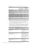
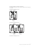
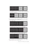
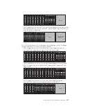
The server can support up to 24 hot-swap drives, using the supported
SAS\SATA backplane configurations. The server supports 2.5-inch hot-swap SAS
or hot-swap SATA hard disk drives, 2.5-inch hot-swap solid state drive, or
1.8-inch hot-swap solid state drives (see “Supported SAS/SATA drive backplane
configurations” on page 283 for more information).
Note:
Configurations with all 1.8-inch drive backplanes can support one
additional simple-swap drive if you purchase the optional Simple-swap 2.5-inch
SATA Drive and Backplate kit.
v
You can mix 2.5-inch hot-swap SAS and SATA hard disk drives, 2.5-inch
hot-swap solid state drive, and 1.8-inch hot-swap solid state drives in the same
server as long as they are not on the same array.
v
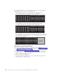
When upgrading drive backplane configurations, all 1.8-inch SSD drive
backplanes must be installed to the right of all 2.5-inch HDD or 2.5-inch SSD
drive backplanes. All 2.5-inch backplanes installs to the left of all 1.8-inch
backplanes. See “IDs for hot-swap drives” on page 282 for drive ID assignment
information and “Supported SAS/SATA drive backplane configurations” on
page 283 for information about the combination of supported drive backplane
configurations.
v
If you install the optional simple-swap SATA drive and backplate assembly, the
backplate must be installed in the backplane slot closest to the information panel
and the SATA drive must be installed in the drive-bay closest to the information
panel.
v
The electromagnetic interference (EMI) integrity and cooling of the server are
protected by having all bays and PCI and PCI Express slots covered or occupied.
When you install a drive, save the EMC shield and filler panel from the bay in
the event that you later remove the device.
v
For a complete list of supported optional devices for the server, see
http://www.ibm.com/servers/eserver/serverproven/compat/us/.
For information on the supported combination of drive backplane configurations,
see “Supported SAS/SATA drive backplane configurations” on page 283.
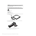
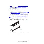
To install a hot-swap drive, complete the following steps:
1.
Read the safety information that begins on page “Safety” on page vii and
“Installation guidelines” on page 261.
2.
Touch the static-protective package that contains the drive to any unpainted
metal surface on the server; then, remove the drive from the package and place
it on a static-protective surface.
3.
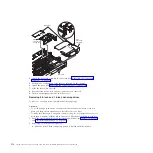
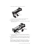
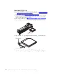
Install a 2.5-inch hot-swap drive:
a.
Make sure that the drive-tray handle is in the open (unlocked) position.
280
System x3690 X5 Types 7147, 7148, 7149, and 7192: Problem Determination and Service Guide
Summary of Contents for System x3690 X5
Page 1: ...System x3690 X5 Types 7147 7148 7149 and 7192 Problem Determination and Service Guide...
Page 2: ......
Page 3: ...System x3690 X5 Types 7147 7148 7149 and 7192 Problem Determination and Service Guide...
Page 8: ...vi System x3690 X5 Types 7147 7148 7149 and 7192 Problem Determination and Service Guide...
Page 13: ...Safety statements Safety xi...
Page 22: ...4 System x3690 X5 Types 7147 7148 7149 and 7192 Problem Determination and Service Guide...
Page 266: ...248 System x3690 X5 Types 7147 7148 7149 and 7192 Problem Determination and Service Guide...
Page 278: ...260 System x3690 X5 Types 7147 7148 7149 and 7192 Problem Determination and Service Guide...
Page 386: ...368 System x3690 X5 Types 7147 7148 7149 and 7192 Problem Determination and Service Guide...
Page 407: ...1 2 Chapter 5 Removing and replacing components 389...
Page 444: ...426 System x3690 X5 Types 7147 7148 7149 and 7192 Problem Determination and Service Guide...
Page 454: ...436 System x3690 X5 Types 7147 7148 7149 and 7192 Problem Determination and Service Guide...
Page 461: ...weight of memory enclosure 28 Index 443...
Page 462: ...444 System x3690 X5 Types 7147 7148 7149 and 7192 Problem Determination and Service Guide...
Page 463: ......
Page 464: ...Part Number 47C8865 Printed in USA 1P P N 47C8865...

