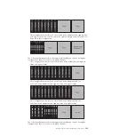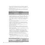
Table 19. non--mirroring mode (normal) DIMM population sequence when one or two
microprocessors and no memory tray is installed (continued)
Pairs of DIMMs
Number of installed
microprocessors
DIMM connector
population sequence with
no memory tray
Pair 2
1 or 2
9, 16
Pair 3
1 or 2
3, 6
Pair 4
1 or 2
11, 14
Pair 5
1 or 2
2, 7
Pair 6
1 or 2
10, 15
Pair 7
1 or 2
4, 5
Pair 8
1 or 2
12, 13
– The following table lists the DIMM installation sequence for non-mirroring
mode when two microprocessors and a memory tray is installed in the server:
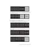
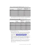
Table 20. Non-mirroring mode (normal) DIMM population sequence when two
microprocessors and a memory tray is installed
Pairs of DIMMs
Number of
installed
microprocessors
DIMM connector
population
sequence on the
system board
DIMM connector
population sequence
on the memory tray
Pair 1
2
1, 8
17, 24
Pair 2
2
9, 16
25, 32
Pair 3
2
3, 6
19, 22
Pair 4
2
11, 14
27, 30
Pair 5
2
2, 7
18, 23
Pair 6
2
10, 15
26, 31
Pair 7
2
4, 5
20, 21
Pair 8
2
12, 13
28, 29
v
Memory-mirroring mode
: When you use the memory mirroring feature,
consider the following information:
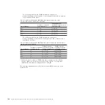
– Memory-mirroring mode replicates and stores data on sets of four DIMMs
simultaneously. If a failure occurs, the memory controller switches from the
set of memory DIMMs to the backup set of DIMMs. To enable memory
mirroring through the Setup utility, select
System Settings
→
Memory
. For
more information, see “Using the Setup utility” on page 402.
– DIMMs must be installed in sets of four. The DIMMs in each set must be the
same size and type. This is applicable also when you have the optional
memory tray installed in the server and the optional IBM MAX5 for System x
attached to the server. You must install DIMMs in sets of four DIMMs for
memory-mirroring mode in each one (the server, memory tray, and the
MAX5).
– The maximum available memory is reduced to half of the installed memory
when memory mirroring is enabled. For example, if you install 64 GB of
memory, only 32 GB of addressable memory is available when you use
memory mirroring.
Chapter 5. Removing and replacing components
299
Summary of Contents for System x3690 X5
Page 1: ...System x3690 X5 Types 7147 7148 7149 and 7192 Problem Determination and Service Guide...
Page 2: ......
Page 3: ...System x3690 X5 Types 7147 7148 7149 and 7192 Problem Determination and Service Guide...
Page 8: ...vi System x3690 X5 Types 7147 7148 7149 and 7192 Problem Determination and Service Guide...
Page 13: ...Safety statements Safety xi...
Page 22: ...4 System x3690 X5 Types 7147 7148 7149 and 7192 Problem Determination and Service Guide...
Page 266: ...248 System x3690 X5 Types 7147 7148 7149 and 7192 Problem Determination and Service Guide...
Page 278: ...260 System x3690 X5 Types 7147 7148 7149 and 7192 Problem Determination and Service Guide...
Page 386: ...368 System x3690 X5 Types 7147 7148 7149 and 7192 Problem Determination and Service Guide...
Page 407: ...1 2 Chapter 5 Removing and replacing components 389...
Page 444: ...426 System x3690 X5 Types 7147 7148 7149 and 7192 Problem Determination and Service Guide...
Page 454: ...436 System x3690 X5 Types 7147 7148 7149 and 7192 Problem Determination and Service Guide...
Page 461: ...weight of memory enclosure 28 Index 443...
Page 462: ...444 System x3690 X5 Types 7147 7148 7149 and 7192 Problem Determination and Service Guide...
Page 463: ......
Page 464: ...Part Number 47C8865 Printed in USA 1P P N 47C8865...

