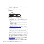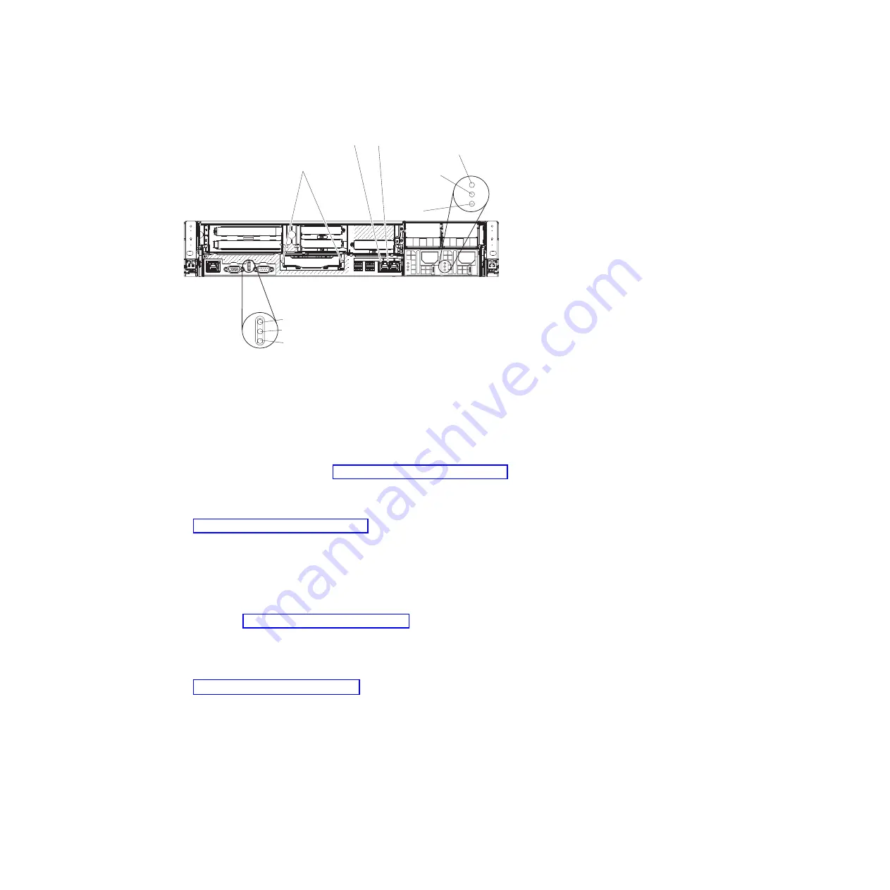
AC LED
(green)
DC LED
(green)
Power-supply
error LED
(amber)
Power-on LED (green)
Locator LED (blue)
System error LED (amber)
Ethernet
activity LED
Ethernet
link LED
QPI link LEDs
v
QPI ports:
Insert either a QPI cable or a filler panel in each of these connectors.
Attention:
When you handle the QPI cables, take precautions to avoid
damaging the high density interface. Dropping and incorrectly connecting the
QPI cables can damage the high density interface. Store the protective covers
that come on the end of the QPI cables for reuse when you perform maintenance
on the server or when you remove the cables for some reason.
v
PCI riser slot 1:
Insert the PCI riser card with two slots or the PCI riser cards
with one slot into this slot. Standard models of the server come with two PCI
Express riser assemblies. See “Replacing an adapter” on page 275 for the
supported adapters for these riser-cards.
v
PCI slot 2:
Insert the PCI riser card with three slots into this slot. Standard
models of the server come with two PCI Express riser assemblies. See
“Replacing an adapter” on page 275 for information about adapters that this
riser card supports.
v
Power connector:
Connect the power cord to this connector.
v
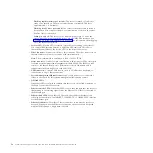
AC power LED:
Each hot-swap power supply has an ac power LED and a dc
power LED. When the ac power LED is lit, it indicates that sufficient power is
being supplied to the power supply through the power cord. During normal
operation, both the ac and dc power LEDs are lit. For any other combination of
LEDs, see “Power-supply LEDs” on page 78.
v
DC power LED:
Each hot-swap power supply has a dc power LED and an ac
power LED. When the dc power LED is lit, it indicates that the power supply is
supplying adequate dc power to the system. During normal operation, both the
ac and dc power LEDs are lit. For any other combination of LEDs, see
“Power-supply LEDs” on page 78.
v
System-error LED:
When this LED is lit, it indicates that a system error has
occurred. An LED on the light path diagnostics panel is also lit to help isolate
the error. This LED is functionally equivalent to the system-error LED on the
front of the server.
v
Power-on LED:
When this LED is lit and not flashing, it indicates that the server
is turned on. This LED is functionally equivalent to the Power-on LED on the
front of the server. The states of the power-on LED are as follows:
Off:
AC power is not present, or the power supply or the LED itself has
failed.
Chapter 2. Introduction
15
Summary of Contents for System x3690 X5
Page 1: ...System x3690 X5 Types 7147 7148 7149 and 7192 Problem Determination and Service Guide...
Page 2: ......
Page 3: ...System x3690 X5 Types 7147 7148 7149 and 7192 Problem Determination and Service Guide...
Page 8: ...vi System x3690 X5 Types 7147 7148 7149 and 7192 Problem Determination and Service Guide...
Page 13: ...Safety statements Safety xi...
Page 22: ...4 System x3690 X5 Types 7147 7148 7149 and 7192 Problem Determination and Service Guide...
Page 266: ...248 System x3690 X5 Types 7147 7148 7149 and 7192 Problem Determination and Service Guide...
Page 278: ...260 System x3690 X5 Types 7147 7148 7149 and 7192 Problem Determination and Service Guide...
Page 386: ...368 System x3690 X5 Types 7147 7148 7149 and 7192 Problem Determination and Service Guide...
Page 407: ...1 2 Chapter 5 Removing and replacing components 389...
Page 444: ...426 System x3690 X5 Types 7147 7148 7149 and 7192 Problem Determination and Service Guide...
Page 454: ...436 System x3690 X5 Types 7147 7148 7149 and 7192 Problem Determination and Service Guide...
Page 461: ...weight of memory enclosure 28 Index 443...
Page 462: ...444 System x3690 X5 Types 7147 7148 7149 and 7192 Problem Determination and Service Guide...
Page 463: ......
Page 464: ...Part Number 47C8865 Printed in USA 1P P N 47C8865...

