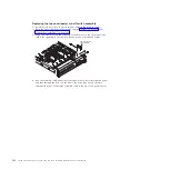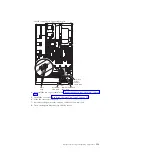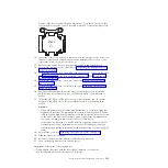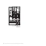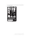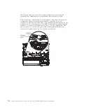
Removing the system board
Before you remove the system board from the server, take the following steps to
save data, firmware, and configuration data:
v
Record all system configuration information, such as IMM IP addresses, vital
product data, and the machine type, model number, serial number, Universally
Unique Identifier, and asset tag of the server.
v
Using the Advanced Settings Utility (ASU), save the system configuration to
external media.
v
Save the system-event log to external media.
Note:
1.
When you replace the system board, you must either update the server with
the latest firmware or restore the pre-existing firmware that the customer
provides on a diskette or CD image. Make sure that you have the latest
firmware or a copy of the pre-existing firmware before you proceed.
2.
Before you attach a MAX5 to the server and try to use it, you must update the
server firmware with the latest level of firmware or code. If you attach and try
to use the MAX5 without updating the server firmware, you might get
unexpected system behavior or the server might not power on. For special
instructions to follow before you attach the MAX5 to the server, go to
http://www.ibm.com/support/entry/portal/docdisplay?lndocid=MIGR-
5085756.
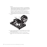
To remove the system board, complete the following steps:
1.
Read the safety information and installation guidelines, see “Safety” on page
vii and “Installation guidelines” on page 261.
2.
Turn off the server (see “Turning off the server” on page 17) and all attached
peripheral devices. Disconnect all power cords; then, disconnect all external
cables as necessary to replace the device.
3.
If the server is in a rack, slide the server out of the rack.
4.
Remove the server cover (see “Removing the server top cover” on page 264).
5.
Disconnect all cables from the system board. Make a list of each cable as you
disconnect it; you can then use this as a checklist when you install the new
system board.
6.
Disconnect all remote RAID battery cables from the adapters, if any are
installed.
7.
Remove the fan cage assembly (see “Removing the fan cage assembly” on
page 331
8.
Remove the DIMM air baffle, if one is installed (see “Removing the DIMM air
baffle” on page 270).
9.
Remove the memory tray, if one is installed (see “Removing the memory tray”
on page 266).
10.
Remove the DIMMs from the system board and set them aside on a
static-protective surface for reinstallation (see “Removing a memory module”
on page 295).
Note:
Make a note of the location of each DIMM as you remove it, so that
you can later reinstall it in the same connector.
11.
Remove all PCI riser-card assemblies with the adapters in them (see
“Removing a PCI riser-card assembly” on page 336).
12.
Remove the microprocessor air baffle (see “Removing the microprocessor air
baffle” on page 268).
360
System x3690 X5 Types 7147, 7148, 7149, and 7192: Problem Determination and Service Guide
Summary of Contents for System x3690 X5
Page 1: ...System x3690 X5 Types 7147 7148 7149 and 7192 Problem Determination and Service Guide...
Page 2: ......
Page 3: ...System x3690 X5 Types 7147 7148 7149 and 7192 Problem Determination and Service Guide...
Page 8: ...vi System x3690 X5 Types 7147 7148 7149 and 7192 Problem Determination and Service Guide...
Page 13: ...Safety statements Safety xi...
Page 22: ...4 System x3690 X5 Types 7147 7148 7149 and 7192 Problem Determination and Service Guide...
Page 266: ...248 System x3690 X5 Types 7147 7148 7149 and 7192 Problem Determination and Service Guide...
Page 278: ...260 System x3690 X5 Types 7147 7148 7149 and 7192 Problem Determination and Service Guide...
Page 386: ...368 System x3690 X5 Types 7147 7148 7149 and 7192 Problem Determination and Service Guide...
Page 407: ...1 2 Chapter 5 Removing and replacing components 389...
Page 444: ...426 System x3690 X5 Types 7147 7148 7149 and 7192 Problem Determination and Service Guide...
Page 454: ...436 System x3690 X5 Types 7147 7148 7149 and 7192 Problem Determination and Service Guide...
Page 461: ...weight of memory enclosure 28 Index 443...
Page 462: ...444 System x3690 X5 Types 7147 7148 7149 and 7192 Problem Determination and Service Guide...
Page 463: ......
Page 464: ...Part Number 47C8865 Printed in USA 1P P N 47C8865...

