Removing and replacing MAX5 Tier 2 CRUs
You may install a Tier 2 CRU yourself or request IBM to install it, at no additional
charge, under the type of warranty service that is designated for your MAX5.
Removing the MAX5 system-board tray assembly
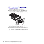
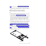
To remove the system-board tray, complete the following steps:
Note:
1.
When you replace the system-board tray, make sure that the host server
firmware is at the latest level.
2.
Before you attach a MAX5 to the server and try to use it, you must update the
server firmware with the latest level of firmware or code. If you attach and try
to use the MAX5 without updating the server firmware, you might get
unexpected system behavior or the server might not power on. For special
instructions to follow before you attach the MAX5 to the server, go to
http://www.ibm.com/support/entry/portal/docdisplay?lndocid=MIGR-
5085756.
1.
Read the safety information and installation guidelines, see “Safety” on page vii
and “Installation guidelines” on page 261.
2.
Turn off the host server (see “Turning off the server” on page 17) and all
attached peripheral devices. Disconnect all power cords; then, disconnect all
external cables from the server. Disconnect all power cords from the MAX5;
then, disconnect all external cables from the MAX5 as necessary to replace the
device.
3.
Remove the bezel (see “Removing the MAX5 bezel” on page 376).
4.
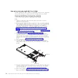
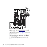
Grasp the blue release latches on the system-board tray handles and press
release latches in opposite directions and rotate the handles to the fully open
position.
Stop-tab
Release latch
Release latch
Stop-tab
Handle
Handle
5.
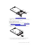
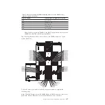
Grasp the handles and pull the system-board tray out until it stops; then, press
inward on the stop-tabs on both sides of the system-board tray and pull the
tray out of the chassis.
6.
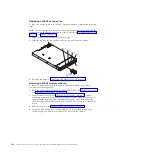
Remove the air baffle (see “Replacing the MAX5 air baffle” on page 378).
7.
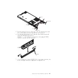
Remove the DIMMs (see “Removing a MAX5 memory module” on page 382).
394
System x3690 X5 Types 7147, 7148, 7149, and 7192: Problem Determination and Service Guide
Summary of Contents for System x3690 X5
Page 1: ...System x3690 X5 Types 7147 7148 7149 and 7192 Problem Determination and Service Guide...
Page 2: ......
Page 3: ...System x3690 X5 Types 7147 7148 7149 and 7192 Problem Determination and Service Guide...
Page 8: ...vi System x3690 X5 Types 7147 7148 7149 and 7192 Problem Determination and Service Guide...
Page 13: ...Safety statements Safety xi...
Page 22: ...4 System x3690 X5 Types 7147 7148 7149 and 7192 Problem Determination and Service Guide...
Page 266: ...248 System x3690 X5 Types 7147 7148 7149 and 7192 Problem Determination and Service Guide...
Page 278: ...260 System x3690 X5 Types 7147 7148 7149 and 7192 Problem Determination and Service Guide...
Page 386: ...368 System x3690 X5 Types 7147 7148 7149 and 7192 Problem Determination and Service Guide...
Page 407: ...1 2 Chapter 5 Removing and replacing components 389...
Page 444: ...426 System x3690 X5 Types 7147 7148 7149 and 7192 Problem Determination and Service Guide...
Page 454: ...436 System x3690 X5 Types 7147 7148 7149 and 7192 Problem Determination and Service Guide...
Page 461: ...weight of memory enclosure 28 Index 443...
Page 462: ...444 System x3690 X5 Types 7147 7148 7149 and 7192 Problem Determination and Service Guide...
Page 463: ......
Page 464: ...Part Number 47C8865 Printed in USA 1P P N 47C8865...

