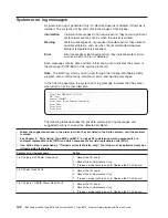


v
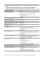
Follow
the
suggested
actions
in
the
order
in
which
they
are
listed
in
the
Action
column
until
the
problem
is
solved.
v
See
Chapter
3,
“Parts
listing,
Type
8878
and
8879,”
on
page
23
to
determine
which
components
are
customer
replaceable
units
(CRU)
and
which
components
are
field
replaceable
units
(FRU).
v
If
an
action
step
is
preceded
by
“(Trained
service
technician
only),”
that
step
must
be
performed
only
by
a
trained
service
technician.
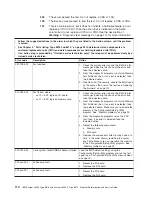
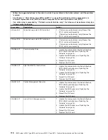
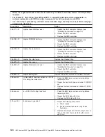
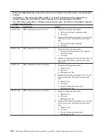
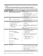
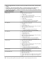
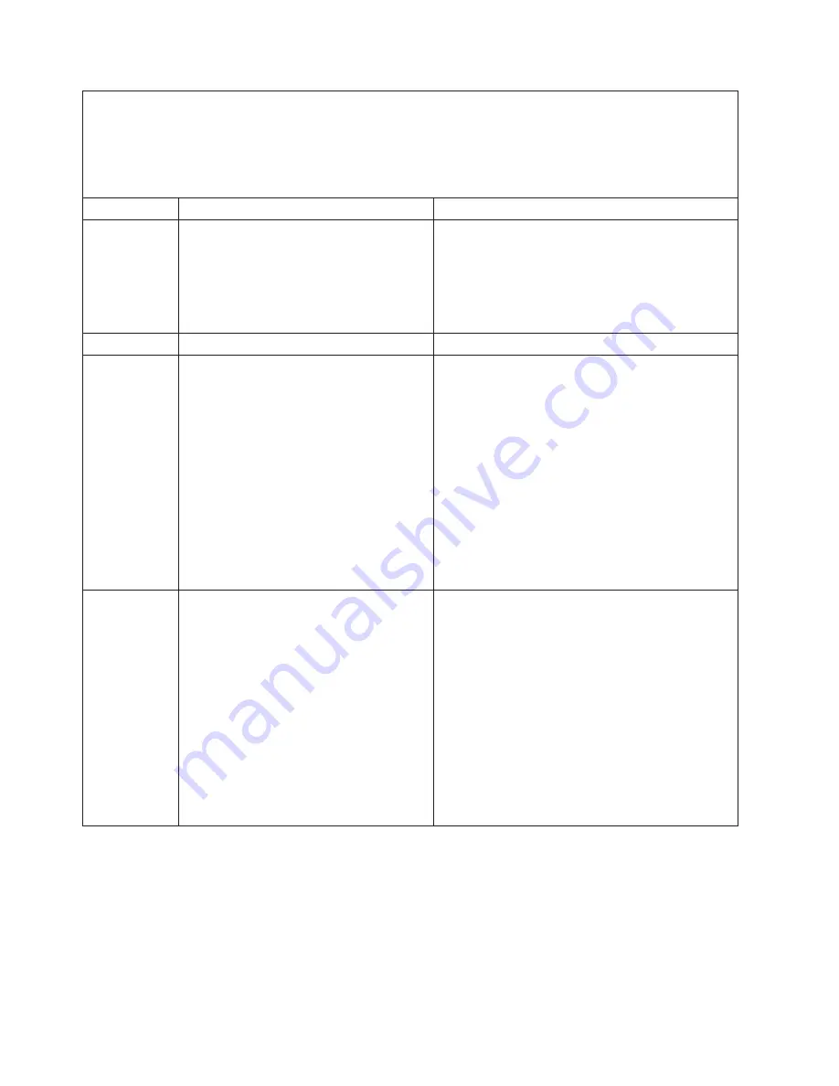
Error
code
Description
Action
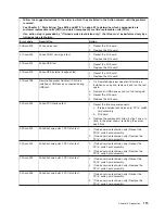
180-361-003
Failed
fan
LED
test.
1.
Reseat
the
following
components:
a.
Fan
b.
I/O
board
2.
Replace
the
components
listed
above
one
at
a
time,
in
the
order
listed
above,
restarting
the
server
each
time.
180-xxx-000
Diagnostics
LED
failure.
Run
the
diagnostic
LED
test
for
the
failing
LED.
180-xxx-001
Failed
front
LED
panel
test.
1.
Reseat
the
following
components:
a.
(Trained
service
technician
only)
Operator
information
panel
b.
I/O
board
c.
Microprocessor
tray
2.
Replace
the
following
components
one
at
a
time,
in
the
order
shown,
restarting
the
server
each
time.
a.
(Trained
service
technician
only)
Operator
information
panel
b.
I/O
board
c.
(Trained
service
technician
only)
Microprocessor
tray
180-xxx-002
Failed
diagnostics
LED
panel
test.
1.
Reseat
the
following
components:
a.
(Trained
service
technician
only)
Operator
information
panel
b.
I/O
board
c.
Microprocessor
tray
2.
Replace
the
following
components
one
at
a
time,
in
the
order
shown,
restarting
the
server
each
time.
a.
(Trained
service
technician
only)
Operator
information
panel
b.
I/O
board
c.
(Trained
service
technician
only)
Microprocessor
tray
126
IBM
System
x3950
Type
8878
and
System
x3950
E
Type
8879:
Problem
Determination
and
Service
Guide
Summary of Contents for System x3950 Type 8878
Page 2: ......
Page 185: ...Japanese Voluntary Control Council for Interference VCCI statement Appendix B Notices 169...
Page 191: ......
Page 192: ...Part Number 31R1891 Printed in USA 1P P N 31R1891...


