

v
Follow
the
suggested
actions
in
the
order
in
which
they
are
listed
in
the
Action
column
until
the
problem
is
solved.
v
See
Chapter
3,
“Parts
listing,
Type
8878
and
8879,”
on
page
23
to
determine
which
components
are
customer
replaceable
units
(CRU)
and
which
components
are
field
replaceable
units
(FRU).
v
If
an
action
step
is
preceded
by
“(Trained
service
technician
only),”
that
step
must
be
performed
only
by
a
trained
service
technician.
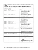
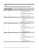
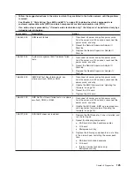
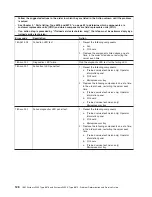
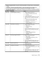
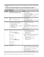
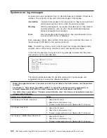
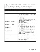
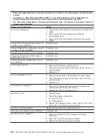
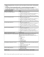
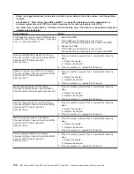
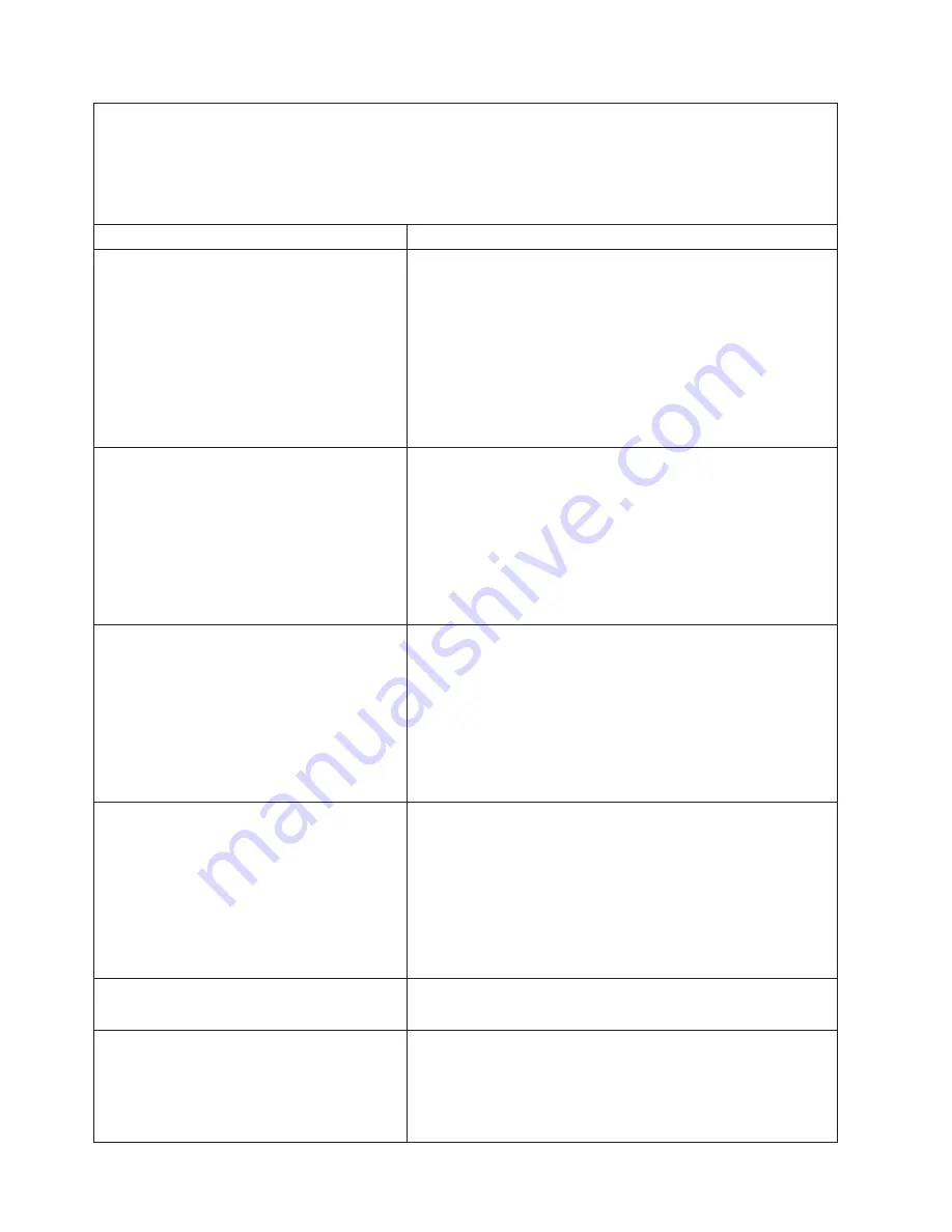
System-error
log
message
Action
12V
B
Bus
Fault
1.
Reseat
the
following
components:
a.
Disk
drives
b.
SAS
hard
disk
drive
backplane
cables
2.
Replace
the
following
components
one
at
a
time,
in
the
order
shown,
restarting
the
server
each
time:
a.
Disk
drives
b.
SAS
hard
disk
drive
backplane
c.
(Trained
service
technician
only)
Power
backplane
d.
(Trained
service
technician
only)
PCI-X
board
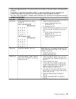
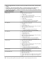
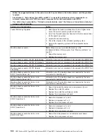
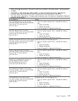
12V
C
Bus
Fault
1.
Reseat
the
following
components:
a.
Adapters
b.
Microprocessor
tray
2.
Replace
the
following
components
one
at
a
time,
in
the
order
shown,
restarting
the
server
each
time:
a.
Adapters
b.
(Trained
service
technician
only)
PCI-X
board
c.
(Trained
service
technician
only)
Power
backplane
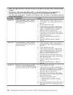
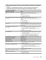
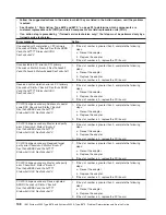
12V
D
Bus
Fault
1.
Reseat
the
following
components:
a.
Microprocessor
tray
b.
Memory
cards
3
and
4
2.
Replace
the
following
components
one
at
a
time,
in
the
order
shown,
restarting
the
server
each
time:
a.
Memory
cards
3
and
4
b.
(Trained
service
technician
only)
Power
backplane
c.
(Trained
service
technician
only)
Microprocessor
tray
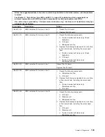
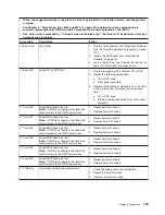
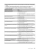
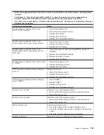
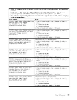
12V
E
Bus
Fault
1.
Reseat
the
following
components:
a.
Microprocessor
tray
b.
Memory
cards
1
and
2
2.
Replace
the
following
components
one
at
a
time,
in
the
order
shown,
restarting
the
server
each
time:
a.
Memory
cards
1
and
2
b.
(Trained
service
technician
only)
Power
backplane
c.
(Trained
service
technician
only)
Microprocessor
tray
12V
Planar
Fault
1.
Reseat
the
microprocessor
tray.
2.
Replace
the
power
backplane.
12V
Power
Good
Fault
1.
Reseat
the
microprocessor
tray.
2.
Reseat
the
memory
cards.
3.
(Trained
service
technician
only)
Replace
the
power
backplane.
4.
(Trained
service
technician
only)
Replace
the
microprocessor
tray.
134
IBM
System
x3950
Type
8878
and
System
x3950
E
Type
8879:
Problem
Determination
and
Service
Guide
Summary of Contents for System x3950 Type 8878
Page 2: ......
Page 185: ...Japanese Voluntary Control Council for Interference VCCI statement Appendix B Notices 169...
Page 191: ......
Page 192: ...Part Number 31R1891 Printed in USA 1P P N 31R1891...


