

v
Follow
the
suggested
actions
in
the
order
in
which
they
are
listed
in
the
Action
column
until
the
problem
is
solved.
v
See
Chapter
3,
“Parts
listing,
Type
8878
and
8879,”
on
page
23
to
determine
which
components
are
customer
replaceable
units
(CRU)
and
which
components
are
field
replaceable
units
(FRU).
v
If
an
action
step
is
preceded
by
“(Trained
service
technician
only),”
that
step
must
be
performed
only
by
a
trained
service
technician.
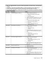
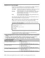
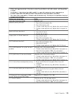
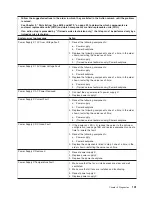
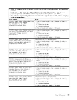
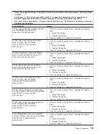
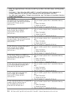
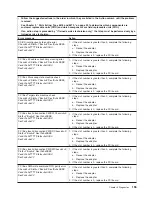
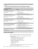
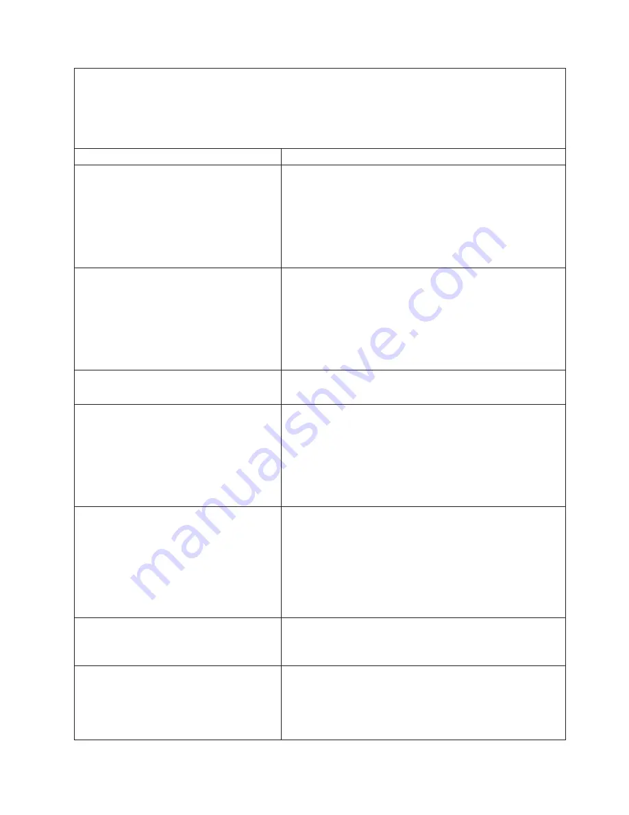
System-error
log
message
Action
Power
Supply
X
12V
Over
Voltage
Fault
1.
Reseat
the
following
components:
a.
Power
supply
b.
Power
backplane
2.
Replace
the
following
components
one
at
a
time,
in
the
order
shown,
restarting
the
server
each
time:
a.
Power
supply
b.
(Trained
service
technician
only)
Power
backplane
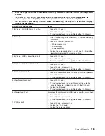
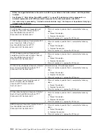
Power
Supply
X
12V
Under
Voltage
Fault
1.
Reseat
the
following
components:
a.
Power
supply
b.
Power
backplane
2.
Replace
the
following
components
one
at
a
time,
in
the
order
shown,
restarting
the
server
each
time:
a.
Power
supply
b.
(Trained
service
technician
only)
Power
backplane
Power
Supply
X
AC
Power
Removed
1.
Connect
the
ac
power
cord
to
power
supply
X.
2.
Replace
power
supply
X.
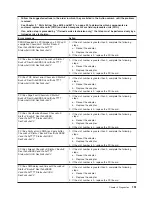
Power
Supply
X
Current
Fault
1.
Reseat
the
following
components:
a.
Power
supply
b.
Power
backplane
2.
Replace
the
following
components
one
at
a
time,
in
the
order
shown,
restarting
the
server
each
time:
a.
Power
supply
b.
(Trained
service
technician
only)
Power
backplane
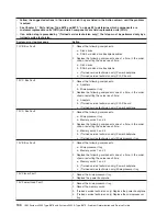
Power
Supply
X
DC
Good
Fault
1.
If
the
power-on
LED
is
lit,
reduce
the
server
to
the
minimum
configuration
(see
page
158)
and
replace
components
one
at
a
time
to
isolate
the
fault.
2.
Reseat
the
following
components:
a.
Power
supply
b.
Power
backplane
3.
Replace
the
components
listed
in
step
2
one
at
a
time,
in
the
order
shown,
restarting
the
server
each
time.
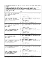
Power
Supply
X
Removed
1.
Reseat
power
supply
X.
2.
Replace
power
supply
X.
3.
Replace
the
power
backplane.
Power
Supply
X
Temperature
Fault
1.
Make
sure
that
the
fan
air
intake
areas
are
clear
and
well
ventilated.
2.
Make
sure
that
all
fans
are
installed
and
functioning.
3.
Reseat
power
supply
X.
4.
Replace
power
supply
X.
Chapter
5.
Diagnostics
141
Summary of Contents for System x3950 Type 8878
Page 2: ......
Page 185: ...Japanese Voluntary Control Council for Interference VCCI statement Appendix B Notices 169...
Page 191: ......
Page 192: ...Part Number 31R1891 Printed in USA 1P P N 31R1891...


