

Attention:
Incomplete
insertion
might
cause
damage
to
the
server
or
the
ServeRAID-8i
adapter.
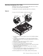
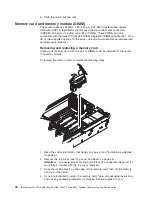
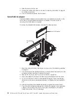
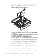
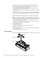
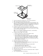
2.
Position
the
ServeRAID-8i
adapter
so
that
the
metal
locking
clasp
is
at
the
rear
of
the
server;
then,
press
the
ServeRAID-8i
adapter
firmly
into
the
connector.
3.
Install
the
top
cover
(see
“Top
cover
and
bezel”).
4.
Slide
the
server
into
the
rack.
5.
Connect
the
cables
and
power
cords
(see
“Connecting
the
cables”
on
page
34
for
cabling
instructions).
6.
Turn
on
all
attached
devices
and
the
server.
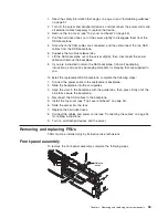
Top
cover
and
bezel
Attention:
Operating
the
server
for
more
than
2
minutes
with
the
top
cover
removed
might
damage
server
components.
For
proper
cooling
and
airflow,
replace
the
top
cover
before
turning
on
the
server.
To
remove
the
top
cover
and
bezel,
complete
the
following
steps:
1.
Read
the
safety
information
that
begins
on
page
“Safety”
on
page
vii
and
“Installation
guidelines”
on
page
31.
2.
If
you
are
installing
or
replacing
a
non-hot-swap
component,
turn
off
the
server
and
all
peripheral
devices,
and
disconnect
the
power
cords
and
all
external
cables.
3.
Slide
the
server
out
of
the
rack
until
the
slide
rails
lock
into
place.
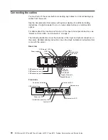
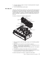
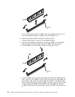
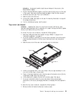
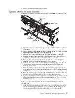
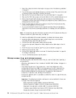
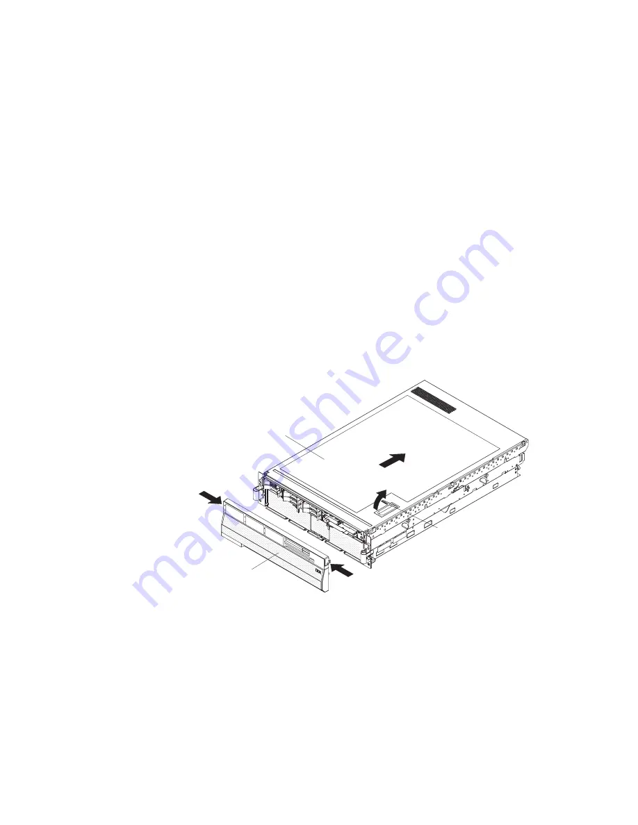
Bezel
Top cover
Cover release
latch
4.
Lift
the
cover-release
latch.
The
cover
slides
to
the
rear
approximately
13
mm
(0.5
inch).
Lift
the
cover
off
the
server.
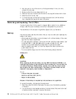
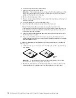
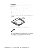
5.
Press
on
the
bezel
retention
tabs
at
the
top
edge
of
the
bezel,
and
pull
the
top
of
the
bezel
slightly
away
from
the
server.
6.
Lift
the
bezel
up
to
release
the
tabs
at
the
bottom
edge
of
the
bezel.
7.
If
you
are
instructed
to
return
the
cover
and
bezel,
follow
all
packaging
instructions,
and
use
any
packaging
materials
for
shipping
that
are
supplied
to
you.
To
install
the
top
cover
and
bezel,
complete
the
following
steps:
1.
Make
sure
that
all
internal
cables
are
correctly
routed.
Chapter
4.
Removing
and
replacing
server
components
45
Summary of Contents for System x3950 Type 8878
Page 2: ......
Page 185: ...Japanese Voluntary Control Council for Interference VCCI statement Appendix B Notices 169...
Page 191: ......
Page 192: ...Part Number 31R1891 Printed in USA 1P P N 31R1891...


