

The
I/O
board
contains
three-pin
jumper
blocks.
See
“I/O
board
internal
connectors
and
jumpers”
on
page
8
for
the
location
and
description
of
each
jumper
block.
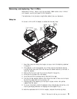
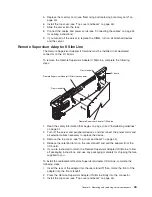
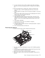
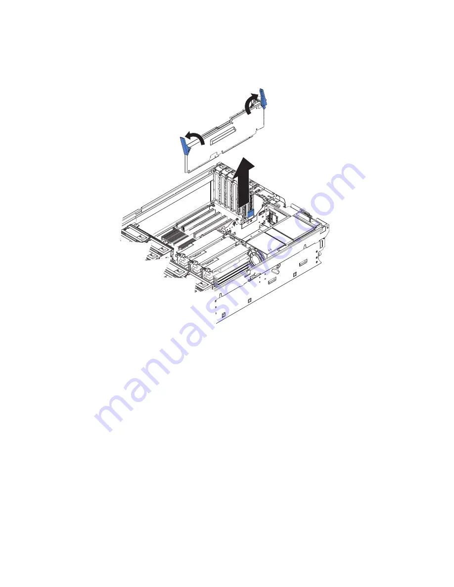
To
remove
the
I/O
board,
complete
the
following
steps:
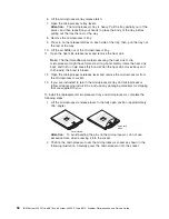
AC
D
C
1.
Read
the
safety
information
that
begins
on
page
vii
and
“Installation
guidelines”
on
page
31.
2.
Turn
off
the
server
and
peripheral
devices,
and
disconnect
the
power
cords
and
all
external
cables
necessary
to
replace
the
device.
3.
Remove
the
top
cover
(see
“Top
cover
and
bezel”
on
page
45).
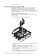
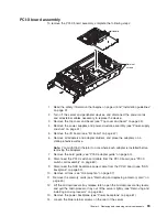
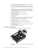
4.
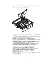
Open
the
release
latches
on
both
ends
of
the
I/O
board
and
pull
the
board
from
the
server
slightly.
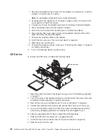
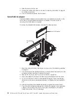
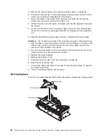
5.
Note
where
each
cable
is
connected,
and
then
disconnect
all
cables
from
the
I/O
board
and
remove
the
assembly
from
the
server.
6.
If
you
are
instructed
to
return
the
I/O
board,
follow
all
packaging
instructions,
and
use
any
packaging
materials
for
shipping
that
are
supplied
to
you.
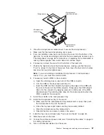
To
install
the
replacement
I/O
board,
complete
the
following
steps:
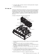
1.
Connect
all
cables
to
the
internal
connectors
on
the
I/O
board.
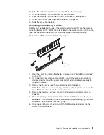
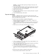
2.
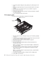
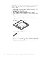
Align
the
board
with
the
card
guides
and
insert
the
board
in
the
connector.
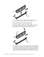
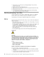
3.
Close
the
release
latches
to
seat
the
board
in
the
connector.
4.
Install
the
top
cover
(see
“Top
cover
and
bezel”
on
page
45).
5.
Slide
the
server
into
the
rack.
6.
Connect
the
cables
and
power
cords
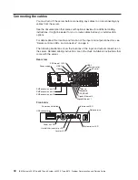
(see
“Connecting
the
cables”
on
page
34
for
cabling
instructions).
48
IBM
System
x3950
Type
8878
and
System
x3950
E
Type
8879:
Problem
Determination
and
Service
Guide
Summary of Contents for System x3950 Type 8878
Page 2: ......
Page 185: ...Japanese Voluntary Control Council for Interference VCCI statement Appendix B Notices 169...
Page 191: ......
Page 192: ...Part Number 31R1891 Printed in USA 1P P N 31R1891...


