
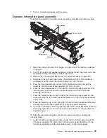

2.
Connect
the
light
path
diagnostics
ribbon
cable
and
front
USB
cable
to
the
I/O
board.
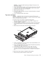
3.
Slide
the
front-panel
assembly
into
the
server
until
the
blue
tab
on
the
chassis
engages.
4.
Install
the
top
cover
and
bezel
(see
“Top
cover
and
bezel”
on
page
45).
5.
Slide
the
server
into
the
rack.
6.
Connect
the
cables
and
power
cords
(see
“Connecting
the
cables”
on
page
34
for
cabling
instructions).
7.
Turn
on
all
attached
devices
and
the
server.
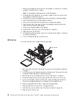
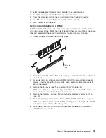
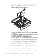
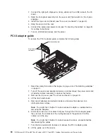
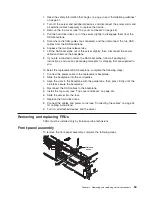
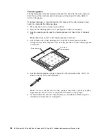
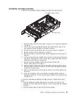
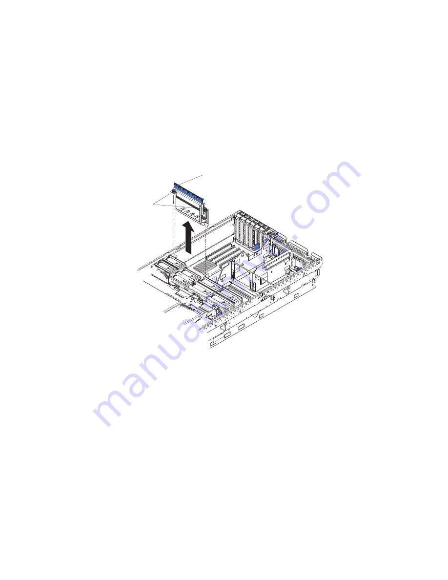
PCI-X
adapter
guide
To
remove
the
PCI-X
adapter
guide,
complete
the
following
steps.
Latch mechanism
Quarter-turn
fasteners
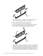
1.
Read
the
safety
information
that
begins
on
page
vii
and
“Installation
guidelines”
on
page
31.
2.
Turn
off
the
server
and
peripheral
devices,
and
disconnect
the
power
cords
and
all
external
cables
necessary
to
replace
the
device.
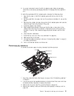
3.
Remove
the
top
cover
(see
“Top
cover
and
bezel”
on
page
45).
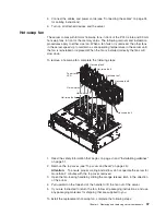
4.
Lift
the
latch
mechanism.
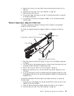
5.
Remove
all
adapters
and
adapter
dividers,
and
place
the
adapters
on
a
static-protective
surface.
Note:
You
might
find
it
helpful
to
note
where
each
adapter
is
installed
before
removing
the
adapters.
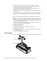
6.
Disconnect
one
end
of
all
cables
that
pass
through
the
PCI-X
adapter
guide;
then,
remove
the
cables
from
the
routing
feature
of
the
guide
and
fold
the
cables
out
of
the
way.
Note:
You
might
find
it
helpful
to
note
where
each
cable
is
connected
before
disconnecting
the
cables.
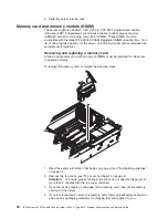
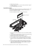
7.
Turn
the
blue
quarter-turn
fasteners
to
release
the
PCI-X
adapter
guide.
8.
Lift
the
guide
out
of
the
server.
50
IBM
System
x3950
Type
8878
and
System
x3950
E
Type
8879:
Problem
Determination
and
Service
Guide
Summary of Contents for System x3950 Type 8878
Page 2: ......
Page 185: ...Japanese Voluntary Control Council for Interference VCCI statement Appendix B Notices 169...
Page 191: ......
Page 192: ...Part Number 31R1891 Printed in USA 1P P N 31R1891...


