
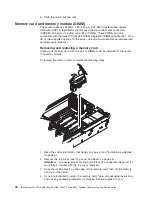
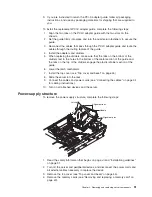

5.
Remove
the
power
supplies
(see
“Hot-swap
power
supply”
on
page
38).
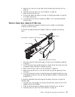
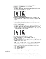
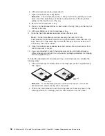
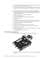
6.
Pull
the
two
blue
latches
on
the
power-supply
structure
toward
the
front
of
the
server;
the
structure
will
disengage
from
the
chassis.
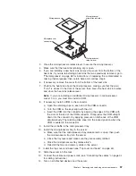
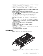
7.
Grasp
the
handle
in
the
middle
of
the
structure
and
rotate
the
structure
up,
allowing
the
structure
to
pivot
at
the
chassis
front.
8.
Lift
the
structure
out
of
the
server,
and
make
sure
that
the
alignment
tabs
clear
the
chassis.
9.
If
you
are
instructed
to
return
the
power-supply
structure,
follow
all
packaging
instructions,
and
use
any
packaging
materials
for
shipping
that
are
supplied
to
you.
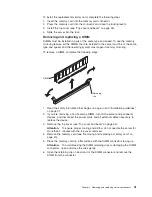
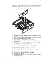
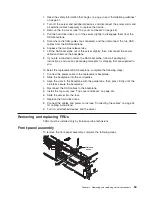
To
install
the
replacement
power-supply
structure,
complete
the
following
steps.
Attention:
Do
not
allow
any
cables
to
be
pinched
or
caught
on
metal
protrusions.
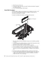
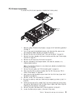
1.
Align
the
tabs
on
the
power-supply
structure
with
the
notches
on
the
rear
of
the
chassis;
then,
gently
lower
the
structure
into
the
server.
Make
sure
that
the
structure
is
firmly
seated
in
the
chassis.
2.
Push
the
two
blue
latches
of
the
power-supply
structure
toward
the
rear
of
the
server
until
they
lock
the
structure
into
position.
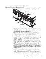
3.
Replace
the
power
supplies.
4.
Replace
the
memory
cards.
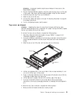
5.
Install
the
top
cover
(see
“Top
cover
and
bezel”
on
page
45).
6.
Slide
the
server
into
the
rack.
7.
Connect
the
cables
and
power
cords
(see
“Connecting
the
cables”
on
page
34
for
cabling
instructions).
8.
Turn
on
all
attached
devices
and
the
server.
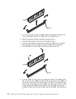
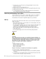
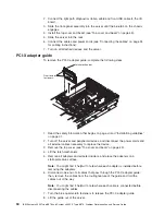
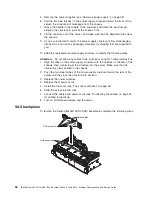
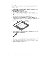
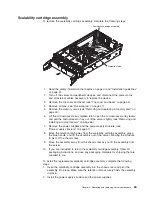
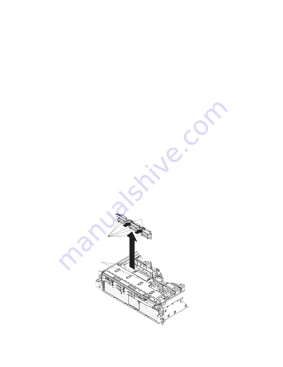
SAS
backplane
To
remove
the
Serial
Attached
SCSI
(SAS)
backplane,
complete
the
following
steps:
Release tabs
Guide channels
SAS connectors
52
IBM
System
x3950
Type
8878
and
System
x3950
E
Type
8879:
Problem
Determination
and
Service
Guide
Summary of Contents for System x3950 Type 8878
Page 2: ......
Page 185: ...Japanese Voluntary Control Council for Interference VCCI statement Appendix B Notices 169...
Page 191: ......
Page 192: ...Part Number 31R1891 Printed in USA 1P P N 31R1891...


