
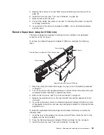
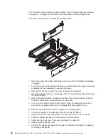

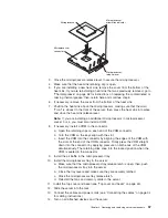
1.
Read
the
safety
information
that
begins
on
page
vii
and
“Installation
guidelines”
on
page
31.
2.
Turn
off
the
server
and
peripheral
devices,
and
disconnect
the
power
cords
and
all
external
cables
necessary
to
replace
the
device.
3.
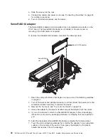
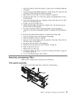
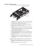
Remove
the
top
cover
(see
“Top
cover
and
bezel”
on
page
45).
4.
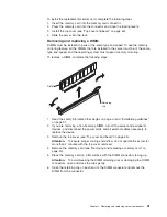
Pull
the
hard
disk
drives
out
of
the
server
slightly
to
disengage
them
from
the
SAS
backplane.
5.
Note
where
the
SAS
cables
are
connected,
and
then
disconnect
the
two
SAS
cables
from
the
SAS
backplane.
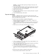
6.
Squeeze
the
two
blue
release
tabs.
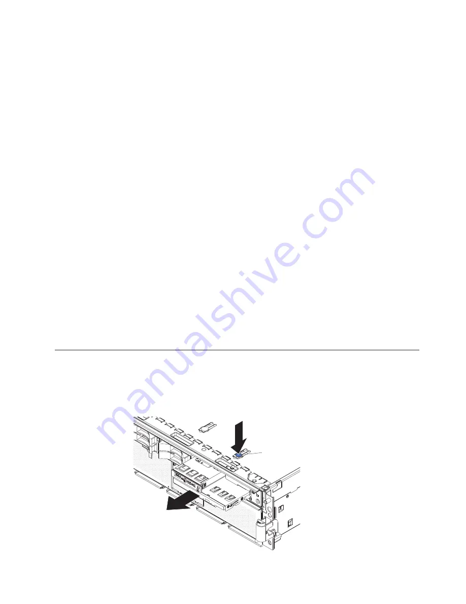
7.
Lift
the
SAS
backplane
out
of
the
server
slightly;
then,
disconnect
the
power
cable
and
remove
the
backplane.
8.
If
you
are
instructed
to
return
the
SAS
backplane,
follow
all
packaging
instructions,
and
use
any
packaging
materials
for
shipping
that
are
supplied
to
you.
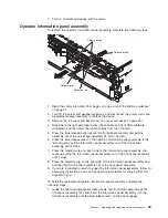
To
install
the
replacement
SAS
backplane,
complete
the
following
steps:
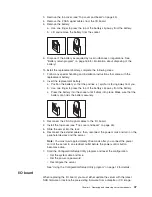
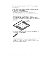
1.
Connect
the
power
cable
to
the
replacement
backplane.
2.
Slide
the
backplane
into
the
card
guides.
3.
Align
the
slots
in
the
backplane
with
the
guide
tabs;
then,
press
firmly
until
the
blue
tabs
secure
the
backplane.
4.
Reconnect
the
SAS
cables
to
the
backplane.
5.
Install
the
top
cover
(see
“Top
cover
and
bezel”
on
page
45).
6.
Slide
the
server
into
the
rack.
7.
Replace
the
hard
disk
drives.
8.
Connect
the
cables
and
power
cords
(see
“Connecting
the
cables”
on
page
34
for
cabling
instructions).
9.
Turn
on
all
attached
devices
and
the
server.
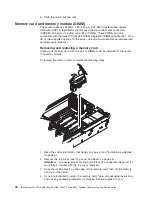
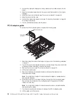
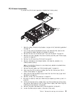
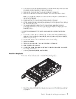
Removing
and
replacing
FRUs
FRUs
must
be
installed
only
by
trained
service
technicians.
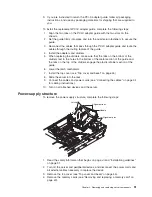
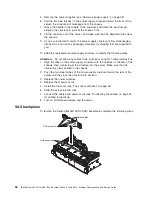
Front-panel
assembly
To
remove
the
front-panel
assembly,
complete
the
following
steps:
Release
button
Chapter
4.
Removing
and
replacing
server
components
53
Summary of Contents for System x3950 Type 8878
Page 2: ......
Page 185: ...Japanese Voluntary Control Council for Interference VCCI statement Appendix B Notices 169...
Page 191: ......
Page 192: ...Part Number 31R1891 Printed in USA 1P P N 31R1891...


