

2.
Turn
off
the
server
and
peripheral
devices,
and
disconnect
the
power
cords
and
all
external
cables
necessary
to
replace
the
device.
3.
Remove
the
top
cover
and
bezel
(see
“Top
cover
and
bezel”
on
page
45).
4.
Remove
all
fans
(see
“Hot-swap
fan”
on
page
37).
5.
Remove
the
memory
cards
(see
“Removing
and
replacing
a
memory
card”
on
page
40).
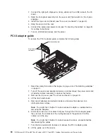
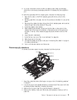
6.
Lift
the
microprocessor-tray
release
latch,
open
the
microprocessor-tray
levers,
and
pull
the
microprocessor
tray
out
of
the
server
slightly
(see
“Removing
and
installing
a
microprocessor”
on
page
55).
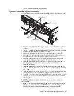
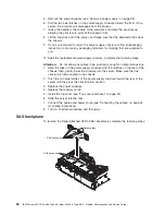
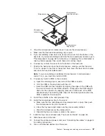
7.
Remove
the
power
supplies
and
the
power-supply
structure
(see
“Power-supply
structure”
on
page
51).
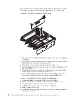
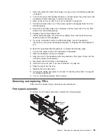
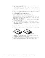
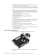
8.
Remove
the
screws
that
secure
the
power
backplane
to
the
chassis
and
lift
the
power
backplane
out
of
the
server.
9.
If
you
are
instructed
to
return
the
power
backplane,
follow
all
packaging
instructions,
and
use
any
packaging
materials
for
shipping
that
are
supplied
to
you.
To
install
the
replacement
power
backplane,
complete
the
following
steps:
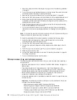
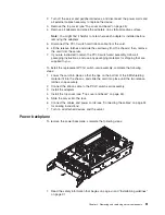
1.
Align
the
power
backplane
in
the
server
and
secure
the
power
backplane
with
screws.
2.
Install
the
power-supply
structure
and
the
power
supplies.
3.
Slide
the
microprocessor
tray
in
the
server
and
close
the
microprocessor-tray
levers.
4.
Install
the
memory
cards.
5.
Install
the
fans.
6.
Install
the
top
cover
and
bezel
(see
“Top
cover
and
bezel”
on
page
45).
7.
Slide
the
server
into
the
rack.
8.
Connect
the
cables
and
power
cords
(see
“Connecting
the
cables”
on
page
34
for
cabling
instructions).
9.
Turn
on
all
attached
devices
and
the
server.
62
IBM
System
x3950
Type
8878
and
System
x3950
E
Type
8879:
Problem
Determination
and
Service
Guide
Summary of Contents for System x3950 Type 8878
Page 2: ......
Page 185: ...Japanese Voluntary Control Council for Interference VCCI statement Appendix B Notices 169...
Page 191: ......
Page 192: ...Part Number 31R1891 Printed in USA 1P P N 31R1891...