background image

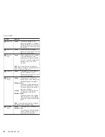
Fn


key


combinations


The


following


table


shows


the


function


of


each


combination


of


Fn


with


a


function


key.


Key


combination


Description


Fn+F1


Reserved.


Fn+F2


Reserved.


Fn+F3


Turn


off


the


LCD


display,


leaving


the


screen


blank.


To


turn


the


LCD


display


on


again,


press


any


key


or


the


TrackPoint


stick.


Fn+F4


Put


the


computer


in


standby


mode.


To


return


to


normal


operation,


press


the


Fn


key


independently,


without


pressing


a


function


key.


Note:


The


setting


can


be


changed


so


that


pressing


it


puts


the


computer


into


hibernation


mode


or


even


shuts


the


computer


down.


Fn+F5


Open


the


Wireless


Radio


Control


screen.


Note:


To


use


this


function,


the


IBM


PM


device


driver


must


be


installed


on


the


computer.


Fn+F6


Reserved.


Fn+F7


Switch


between


the


computer


display


and


an


external


monitor


(CRT).


If


an


external


monitor


is


attached,


computer


output


is


displayed


in


the


following


three


patterns


in


turn:


v


CRT


display


v


Computer


display


+


CRT


display


v


Computer


display

Note:


This


setting


can


be


changed


so


that


pressing


it


starts


a


presentation


scheme


directly


with


no


need


to


start


Presentation


Director.


Fn+F9


Open


the


EasyEject


Utility


screen.


Note:


This


function


is


supported


only


in


Windows


XP


and


Windows


2000.


Fn+F10


Reserved.


Fn+F11


Reserved.


Fn+F12


Put


the


computer


into


hibernation


mode.


To


return


to


normal


operation,


press


the


power


button


for


less


than


four


seconds.


Note:


To


use


Fn+F12


for


hibernation,


the


IBM


PM


device


driver


must


be


installed


on


the


computer.


Fn+Home


The


computer


display


becomes


brighter.


Fn+End


The


computer


display


becomes


less


bright.


Fn+Spacebar


Enable


the


FullScreen


Magnifier


function.


Product


overview


ThinkPad


G40,


G41


49

Summary of Contents for ThinkPad G40 Series

Page 1: ...IBM Mobile Systems ThinkPad Computer Hardware Maintenance Manual August 2004 This manual supports ThinkPad G40 G41...

Page 2: ...ypographical errors Changes are periodically made to the information herein these changes will be incorporated in new editions of the publication IBM may make improvements or changes to the products o...

Page 3: ...ervice information 28 Service Web site 28 Restoring the preloaded system 28 Passwords 30 Power management 33 Checkout guide 35 Testing the computer 35 Detecting system information with PC Doctor 37 Po...

Page 4: ...3 GHz and CPU fixture 93 2010 CPU 95 2020 CD ROM DVD drive bracket 96 2030 FDD bracket 97 2040 System board 98 2050 Lower case assembly 99 2060 Modem cable 100 2070 PC card slot assembly 101 2080 LCD...

Page 5: ...g computers v The product specific section includes service reference and product specific parts information Important This manual is intended for trained service personnel who are familiar with Think...

Page 6: ...2 ThinkPad G40 G41...

Page 7: ...the replacement does not correct the problem reinstall the original FRU before you continue v Some computers have both a processor board and a system board If you are instructed to replace either the...

Page 8: ...layed on the screen to diagnose failures If more than one error code is displayed begin the diagnosis with the first error code Whatever causes the first error code may also cause false error codes If...

Page 9: ...n en place et bien fix es Pour ce faire secouez l unit et assurez vous qu aucun bruit suspect ne se produit Des pi ces m talliques ou des copeaux de m tal pourraient causer un court circuit Bevor nach...

Page 10: ...ue todos los tornillos muelles y dem s piezas peque as se encuentran en su sitio y no se encuentran sueltas dentro del sistema Compru belo agitando el sistema y escuchando los posibles ruidos que prov...

Page 11: ...garde ou celle de l horloge temps r el veillez n utiliser que les mod les cit s dans la liste de pi ces d tach es ad quate Une batterie ou une pile inappropri e risque de prendre feu ou d exploser Die...

Page 12: ...utilizzare soltanto i tipi inseriti nell appropriato Catalogo parti L impiego di una batteria non adatta potrebbe determinare l incendio o l esplosione della batteria stessa Algunas bater as de reser...

Page 13: ...batterie inappropri e risque de prendre feu ou d exploser Akkus enthalten geringe Mengen von Nickel Sie d rfen nicht zerlegt wiederaufgeladen kurzgeschlossen oder Feuer oder Wasser ausgesetzt werden B...

Page 14: ...ni las eche al fuego o al agua ni las cortocircuite Des chelas tal como dispone la normativa local Utilice s lo bater as que se encuentren en la lista de piezas al sustituir la bater a La utilizaci n...

Page 15: ...temperature sup rieure 100 C ne la faites pas br ler et n en exposez pas le contenu l eau Mettez la pile au rebut conform ment la r glementation en vigueur Une pile inappropri e risque de prendre feu...

Page 16: ...iva in vigore DPR 915 82 successive disposizioni e disposizioni locali L impiego di una batteria non adatta potrebbe determinare l incendio o l esplosione della batteria stessa La bater a de repuesto...

Page 17: ...zerbrechen wenn er unsachgem behandelt wird oder der Computer auf den Boden f llt Wenn der Bildschirm besch digt ist und die darin befindliche Fl ssigkeit in Kontakt mit Haut und Augen ger t sollten d...

Page 18: ...re de la carte d alimentation Aus Sicherheitsgr nden die Kunststoffabdeckung die den unteren Teil der Spannungswandlerplatine umgibt nicht entfernen Per evitare scosse elettriche non rimuovere la cope...

Page 19: ...e Spannung haben k nnen sie doch bei Kurzschlu oder Erdung genug Strom abgeben um brennbare Materialien zu entz nden oder Verletzungen bei Personen hervorzurufen Sebbene le batterie di alimentazione s...

Page 20: ...ns d interface Die Stromzufuhr mu abgeschaltet alle Stromkabel aus der Steckdose gezogen der Akku entfernt und alle Verbindungskabel abgenommen sein bevor eine FRU entfernt wird Prima di rimuovere qua...

Page 21: ...ent unsafe v Before you start the machine ensure that other service representatives and the customer s personnel are not in a hazardous position v Place removed covers and other parts in a safe place...

Page 22: ...sulate you when working with live electrical currents Many customers have near their equipment rubber floor mats that contain small conductive fibers to decrease electrostatic discharges Do not use th...

Page 23: ...en measuring high voltages v Regularly inspect and maintain your electrical hand tools for safe operational condition v Do not use worn or broken tools and testers v Never assume that power has been d...

Page 24: ...apacitor v Mechanical hazards such as loose or missing hardware To determine whether there are any potentially unsafe conditions use the following checklist at the beginning of every service task Begi...

Page 25: ...in protective packages until they are inserted into the product v Avoid contact with other people v Wear a grounded wrist strap against your skin to eliminate static on your body v Prevent the part f...

Page 26: ...ipped from the factory with an optical storage device such as a CD ROM drive or a DVD ROM drive They are also sold separately as options The drive is certified in the U S to conform to the requirement...

Page 27: ...des commandes ainsi que les proc dures d crites Werden Steuer und Einstellelemente anders als hier festgesetzt verwendet kann gef hrliche Laserstrahlung auftreten L utilizzo di controlli regolazioni...

Page 28: ...t vitez de fixer le faisceau de le regarder directement avec des instruments optiques ou de vous exposer au rayon Laserstrahlung bei ge ffnetem Ger t Nicht direkt oder ber optische Instrumente in den...

Page 29: ...eplace FRUs only for the correct model When you replace a FRU make sure the model of the machine and the FRU part number are correct by referring to the FRU parts list v A FRU should not be replaced b...

Page 30: ...llowing are not covered under warranty v LCD panel cracked from the application of excessive force or from being dropped v Scratched cosmetic parts v Distortion deformation or discoloration of the cos...

Page 31: ...v If the spindle of a hard disk drive becomes noisy it may have been subjected to excessive force or dropped Read this first General descriptions 27...

Page 32: ...t Recovery program is on the new hard disk In this case you must use the Product Recovery CD for the computer Order the recovery CD and the hard disk drive at the same time so that you can recover the...

Page 33: ...a will be visible and can be reclaimed by the OS Once the area is overwritten by OS tools it can t be used with Normal or Secure again and you will need to obtain a Recovery CD to retrieve original HD...

Page 34: ...t Recovery program Y N v To install the Access IBM Predesktop Area go to step 4 v To preload the hard disk drive without installing the Access IBM Predesktop Area press the N key 8 If you get a messag...

Page 35: ...IBM does not provide any services to reset either the user or the master HDP or to recover data from the hard disk drive The hard disk drive can be replaced for a scheduled fee Supervisor password A s...

Page 36: ...password Attention If User only mode is selected and the user HDP has been forgotten and cannot be made available to the servicer IBM does not provide any services to reset the user HDPs or to recove...

Page 37: ...wered off v The hard disk drive is powered off v The CPU stops To enter standby mode press Fn F4 Note You can change the action of Fn F4 if you are using the ACPI operating system In certain circumsta...

Page 38: ...automatically in either of the following conditions v If a hibernation time has been set on the timer and the user does not do any operation with the keyboard the TrackPoint the hard disk drive the pa...

Page 39: ...ations of the computer PC Doctor might not run correctly To avoid this problem you need to initialize the computer setup by use of the IBM BIOS Setup Utility before you run PC Doctor On the IBM BIOS S...

Page 40: ...v Communication v Wireless LAN v Memory Test Full v Memory Test Quick v Keyboard v Video v Internal Speaker v Mouse v Diskette v System Load v CD ROM DVD Test v Actiontec Wireless Radio Notes v In th...

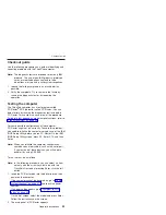
Page 41: ...tem v DOS Shell v Tech Support Form v Battery Rundown v View Test Log v Print Log v Save Log v Full Erase Hard Drive v Quick Erase Hard Drive Power system checkout To verify a symptom do the following...

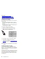
Page 42: ...ge V dc 1 Vcc_ 16V 2 Ground 3 Vcc_ 16V 4 Ground 3 If the voltage is not correct replace the ac adapter 4 If the voltage is acceptable do the following v Replace the system board v If the problem persi...

Page 43: ...on Note If the battery pack becomes hot it may not be able to charge Remove it from the computer and leave it at room temperature for a while After it cools down reinstall and recharge it To check the...

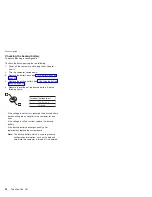
Page 44: ...ltage of the backup battery See the following figure Terminal Voltage V dc 2 5 to 3 2 Ground v If the voltage is not correct recharge the backup battery by connecting the ac adapter to the computer fo...

Page 45: ...MM 67 1050 Modem daughter card MDC 68 1060 Backup battery 69 1070 Keyboard 70 1080 Middle cover 72 1090 Hinge cover 73 1095 FDD assembly 74 1100 Blank bezel FDD assembly 75 1110 VGA heatsink assembly...

Page 46: ...CD FRUs 143 14 1 in TFT 144 15 in TFT 144 Keyboard 146 Recovery CDs 147 Windows XP Home Edition for G40 147 Windows XP Home Edition for G41 147 Windows XP Professional for G40 148 Windows XP Professio...

Page 47: ...us v LPC bus v 333 MHz DDR SDRAM PC2700 Memory standard v 128 MB DDR SDRAM SO DIMM PC2700 card 1 v 256 MB DDR SDRAM SO DIMM PC2700 card 1 v 512 MB DDR SDRAM SO DIMM PC2700 card 1 Memory optional v 128...

Page 48: ...mouse connector v Universal serial bus USB connector 4 Audio v Internal monaural speaker v Software control volume Mini PCI adapter v IEEE 802 11b wireless LAN card v IEEE 802 11a b wireless LAN Comb...

Page 49: ...7 4 5 6 Indicator Meaning 1 Wireless status Green Wireless is operational This indicator is on when the Wireless is on and not in suspend mode Blinking green Data is being transmitted Note The wireles...

Page 50: ...d ready to use This indicator stays lit whenever the computer is on and is not in standby mode 6 Battery status Green The battery is in use and has enough power The ac adapter has charged the battery...

Page 51: ...Card Wrap Plug into every PC Card Slot and run Diagnostics Systemboard PCMCIA External Loop Keyboard 1 Diagnostics Systemboard Keyboard 2 Interactive Tests Keyboard TrackPoint or pointing device If t...

Page 52: ...Diagnostics Memory Test Quick 2 If the problem does not recur return the DIMM to its place remove the other one and run the test again 3 If the test does not detect the error run Diagnostics Memory T...

Page 53: ...between the computer display and an external monitor CRT If an external monitor is attached computer output is displayed in the following three patterns in turn v CRT display v Computer display CRT di...

Page 54: ...tem operation In the displays n can be any number If no numeric code is displayed check the narrative descriptions of symptoms If the symptom is not described there go to Intermittent problems on page...

Page 55: ...retry count exceeded 1 Confirm supervisor password and try again 2 Run IBM BIOS Setup Utility 01C9 More than one Ethernet devices are found Remove one of them Press Esc to continue 1 Remove either a M...

Page 56: ...ration 2 Replace the backup battery and run IBM BIOS Setup Utility to reset the time and date 3 System board 0270 Real time clock error 1 Recharge the backup battery for one hour by connecting the ac...

Page 57: ...1 to open the IBM BIOS Setup Utility Select Security IBM Predesktop Area Access IBM Predesktop Area Set this item to Disabled Save and Exit 2 If the Access IBM Predesktop Area has been previously disa...

Page 58: ...a 1 DIMM 2 System board I O device IRQ conflict 1 Load Setup Defaults in IBM BIOS Setup Utility 2 Recharge the backup battery for one hour by connecting the ac adapter to the computer and run IBM BIOS...

Page 59: ...ce C WINDOWS EMM386 EXE RAM to device C WINDOWS EMM386 EXE NOEMS and save this file CardBus Configuration Error Device Disabled Press F1 to go to the IBM BIOS Setup Utility Press F9 and then Enter to...

Page 60: ...short beep Only cursor appears Reinstall operating system Five short beeps and a blank screen System board No beep symptoms Symptom or error FRU or action in sequence No beep power on indicator on LC...

Page 61: ...of 16 or more bright and dark dots Note A bright dot means a pixel is always on white or color A dark dot means a pixel is always off black color Symptom or error FRU or action in sequence No beep po...

Page 62: ...em is inoperative Follow these procedures to isolate the failing FRU do not isolate FRUs that have no defects Verify that all attached devices are supported by the computer Verify that the power suppl...

Page 63: ...ould be used only once Do the following when you service this machine v Keep the screw kit for the P N see Miscellaneous parts on page 150 in your tool bag v Always use new screws v Use a torque screw...

Page 64: ...iginal serial number by doing the following 1 Install the ThinkPad hardware maintenance diskette version 1 69 or later and restart the computer 2 From the main menu select 1 Set System Identification...

Page 65: ...the same number When you replace the system board you must set the UUID on the new system board as follows 1 Install the ThinkPad hardware maintenance diskette version 1 69 or later and restart the co...

Page 66: ...ing 7 To put the new FRU in place reverse the removal procedure and follow any notes that pertain to replacement For information about connecting and arranging internal cables see Locations on page 10...

Page 67: ...pack DANGER Use only the battery in the parts listing for the model you are servicing Use of an incorrect battery can result in ignition or explosion of the battery Removing and replacing a FRU ThinkP...

Page 68: ...have the user make a backup copy of all the information on the drive if possible v Never remove the drive while the system is operating or is in suspend mode For access remove this FRU v 1010 Battery...

Page 69: ...3 4 When installing Make sure that the hard disk connector is firmly attached Removing and replacing a FRU ThinkPad G40 G41 65...

Page 70: ...ccess remove this FRU v 1010 Battery pack on page 63 Note Loosen the screws 1 but do not remove them Step Screw quantity Torque 1 M2 5 captive screw 2 Nm 0 3 Nm 3 2 kgfcm Removing and replacing a FRU...

Page 71: ...page 66 When installing With the notched end of the DIMM toward the socket insert the DIMM into the socket and then press it firmly Pivot the DIMM until it snaps into place Make sure that the card is...

Page 72: ...hter card MDC For access remove this FRU v 1010 Battery pack on page 63 v 1030 DIMM door on page 66 Step Screw quantity Torque 1 M2 5 x 5 mm Silver 2 Nm 0 3 3 2 kgfcm Removing and replacing a FRU 68 T...

Page 73: ...ting for the computer you are servicing Use of an incorrect battery can result in ignition or explosion of the battery For access remove these FRUs in order v 1010 Battery pack on page 63 v 1030 DIMM...

Page 74: ...Keyboard For access remove these FRUs in order v 1010 Battery pack on page 63 1 Step Screw quantity Torque 1 M2 5 7 mm Black 2 Nm 0 3 3 2 kgfcm continued Removing and replacing a FRU 70 ThinkPad G40...

Page 75: ...the keyboard from the bottom while at the same time pushing a little in the direction of the arrow in step 3 Take care not to bend the keyboard when lifting it at step 4 5 Removing and replacing a FRU...

Page 76: ...n page 63 v 1070 Keyboard on page 70 Step Screw quantity Torque 1 M2 5 8 mm Black 1 Nm 0 3 3 2 kgfcm Note The bottom side screw that secures the middle cover may be a security or tamper proof screw fo...

Page 77: ...access remove this FRU v 1010 Battery pack on page 63 v 1070 Keyboard on page 70 v 1080 Middle cover on page 72 When installing Align the hinge cover squarely and push down Removing and replacing a FR...

Page 78: ...bly For access remove these FRUs in order v 1010 Battery pack on page 63 v 1070 Keyboard on page 70 Step Screw quantity Torque 1 M2 5 5 mm Silver 1 0 3 Nm 3 2 kgfcm Removing and replacing a FRU 74 Thi...

Page 79: ...1010 Battery pack on page 63 v 1070 Keyboard on page 70 2 2 1 Step Screw quantity Torque 1 M2 0 4 mm Silver 2 0 3 Nm 3 2 kgfcm 2 When Installing Be sure the corners of the FDD cover go under the clasp...

Page 80: ...embly For access remove these FRUs in order v 1010 Battery pack on page 63 v 1070 Keyboard on page 70 1 1 2 Step Screw quantity Torque 1 M2 0 4 mm Silver 3 0 3 Nm 3 2 kgfcm Removing and replacing a FR...

Page 81: ...these FRUs in order v 1010 Battery pack on page 63 v 1070 Keyboard on page 70 v 1110 VGA heatsink assembly on page 76 1 5 4 2 3 Step Screw quantity Torque 4 M2 0 4 mm Silver 1 0 3 Nm 3 2 kgfcm Removin...

Page 82: ...et For access remove these FRUs in order v 1010 Battery pack on page 63 v 1070 Keyboard on page 70 1 2 Step Screw quantity Torque 1 M2 5 stud Phillips 5 mm Silver 1 0 3 Nm 3 2 kgfcm 3 3 Removing and r...

Page 83: ...1140 Mini PCI adapter For access remove these FRUs in order v 1010 Battery pack on page 63 v 1070 Keyboard on page 70 v 1080 Middle cover on page 72 Removing and replacing a FRU ThinkPad G40 G41 79...

Page 84: ...or on page 66 v 1070 Keyboard on page 70 v 1080 Middle cover on page 72 v 1090 Hinge cover on page 73 v 1130 CD ROM DVD drive and ODD bracket on page 78 v 1140 Mini PCI adapter on page 79 Step Screw q...

Page 85: ...ard slot assembly from the system board Step Screw quantity Torque 2 M2 5 8 mm Black 2 0 3 Nm 3 2 kgfcm Push the PC card eject buttons 4 to pop the buttons out While holding the PC card door down pull...

Page 86: ...oth screws have caught the first threads of the screw holes on the PC card slot assembly Then tighten each screw one turn at a time alternating between screws to evenly pull the assembly connector ont...

Page 87: ...FRUs in order v 1010 Battery pack on page 63 v 1070 Keyboard on page 70 v 1080 Middle cover on page 72 v 1090 Hinge cover on page 73 1 Step Screw quantity Torque 1 M2 5 7 mm Black 2 0 3 Nm 3 2 kgfcm 2...

Page 88: ...GA connector for non FDD models is as shown below 4 5 4 Step Screw quantity Torque 4 M 2 5 7 mm Black 9 0 3 Nm 3 2 kgfcm 5 M 2 5 3 mm Silver 1 0 3 Nm 3 2 kgfcm 6 continued Removing and replacing a FRU...

Page 89: ...When installing Make sure the red band A on the LCD cable is aligned with the corner of the keyboard bezel under the hinge A Removing and replacing a FRU ThinkPad G40 G41 85...

Page 90: ...der v 1010 Battery pack on page 63 v 1070 Keyboard on page 70 v 1080 Middle cover on page 72 v 1090 Hinge cover on page 73 1 Step Screw quantity Torque 1 M2 5 7 mm Black 2 0 3 Nm 3 2 kgfcm 2 3 continu...

Page 91: ...Non FDD models The VGA connector for non FDD models is as shown below 4 4 5 Step Screw quantity Torque 4 M 2 5 7 mm Silver 4 0 3 Nm 3 2 kgfcm continued Removing and replacing a FRU ThinkPad G40 G41 87...

Page 92: ...When installing Make sure the red band A on the LCD cable is aligned with the corner of the keyboard bezel under the hinge A Removing and replacing a FRU 88 ThinkPad G40 G41...

Page 93: ...oor on page 66 v 1070 Keyboard on page 70 v 1080 Middle cover on page 72 v 1090 Hinge cover on page 73 v 1170 LCD assembly on page 86 1 2 1 Step Screw quantity Torque 1 M 2 5 7 mm Black 9 0 3 Nm 3 2 k...

Page 94: ...Remove the keyboard bezel in the direction of arrow 3 Removing and replacing a FRU 90 ThinkPad G40 G41...

Page 95: ...ge cover on page 73 v 1160 LCD and Keyboard bezel assembly on page 83 To prevent the CPU from being pulled from the socket when the fan is removed remove the screw 2 and reinsert it 3 Then carefully t...

Page 96: ...h the provided spatula Do not apply thermal grease directly to the CPU Then when the fan is in place tighten the screws in this order A B and C Caution When installing be sure the screw that was moved...

Page 97: ...e 72 v 1090 Hinge cover on page 73 v 1160 LCD and Keyboard bezel assembly on page 83 To prevent the CPU from being pulled from the socket when the fan is removed remove the screw 2 and reinsert it 3 T...

Page 98: ...h the provided spatula Do not apply thermal grease directly to the CPU Then when the fan is in place tighten the screws in this order A B and C Caution When installing be sure the screw that was moved...

Page 99: ...l assembly on page 83 v 1190 Fan assembly on page 91 v 2000 Fan CPU 3 GHz and CPU fixture on page 93 Rotate the head of the screw in the direction of the arrow 1 to release the lock then remove the CP...

Page 100: ...page 63 v 1030 DIMM door on page 66 v 1070 Keyboard on page 70 v 1080 Middle cover on page 72 v 1090 Hinge cover on page 73 v 1160 LCD and Keyboard bezel assembly on page 83 1 2 Step Screw quantity To...

Page 101: ...Keyboard on page 70 v 1080 Middle cover on page 72 v 1090 Hinge cover on page 73 v 1160 LCD and Keyboard bezel assembly on page 83 v 1095 FDD assembly on page 74 3 1 2 Step Screw quantity Torque 1 M2...

Page 102: ...DD bracket on page 78 v 1140 Mini PCI adapter on page 79 v 1160 LCD and Keyboard bezel assembly on page 83 v 1190 Fan assembly on page 91 v 2010 CPU on page 95 v 2000 Fan CPU 3 GHz and CPU fixture on...

Page 103: ...ver on page 72 v 1090 Hinge cover on page 73 v 1130 CD ROM DVD drive and ODD bracket on page 78 v 1140 Mini PCI adapter on page 79 v 1160 LCD and Keyboard bezel assembly on page 83 v 2020 CD ROM DVD d...

Page 104: ...over on page 73 v 1140 Mini PCI adapter on page 79 v 1130 CD ROM DVD drive and ODD bracket on page 78 v 1140 Mini PCI adapter on page 79 v 1170 LCD assembly on page 86 v 1180 Keyboard bezel on page 89...

Page 105: ...40 Mini PCI adapter on page 79 v 1130 CD ROM DVD drive and ODD bracket on page 78 v 1140 Mini PCI adapter on page 79 v 1160 LCD and Keyboard bezel assembly on page 83 v 2020 CD ROM DVD drive bracket o...

Page 106: ...removing screws 1 detach all of the latches 2 to 4 in order Step Screw quantity Torque 1 M2 5 5 mm Black 2 0 3 Nm 3 2 kgfcm When installing Make sure that all of the latches of the LCD front bezel ar...

Page 107: ...on page 102 1 3 1 2 4 5 3 Step Screw quantity Torque 1 M2 5 5 mm Silver 2 0 3 Nm 3 2 kgfcm When installing Make sure that connectors 3 4 and 5 are firmly attached Some models have an extra connector...

Page 108: ...e 63 v 2080 LCD front bezel on page 102 v 2090 Inverter card on page 103 2 1 Step Screw quantity Torque 1 M2 5 5 mm Silver 1 0 3 Nm 3 2 kgfcm When installing Make sure the LCD cable is not pinched and...

Page 109: ...66 v 1070 Keyboard on page 70 v 1080 Middle cover on page 72 v 1090 Hinge cover on page 73 v 1170 LCD assembly on page 86 v 2080 LCD front bezel on page 102 v 2090 Inverter card on page 103 1 1 Step S...

Page 110: ...2 3 3 4 When installing Make sure the LCD cable is not pinched and aligned to the left of the speaker Removing and replacing a FRU 106 ThinkPad G40 G41...

Page 111: ...Keyboard on page 70 v 1080 Middle cover on page 72 v 1090 Hinge cover on page 73 v 1170 LCD assembly on page 86 v 2080 LCD front bezel on page 102 v 2090 Inverter card on page 103 v 3010 LCD cable ass...

Page 112: ...070 Keyboard on page 70 v 1090 Hinge cover on page 73 v 1170 LCD assembly on page 86 v 2080 LCD front bezel on page 102 v 2090 Inverter card on page 103 v 3010 LCD cable assembly on page 105 Step Scre...

Page 113: ...r status indicators 3 Power switch 4 PC card slots 5 PC card eject button 6 CD DVD drive eject button 7 CD DVD drive 8 TrackPoint stick 9 TrackPoint buttons 10 Access IBM button 11 Volume control butt...

Page 114: ...ector 2 Modem connector 3 Ethernet connector 4 Universal serial bus USB connectors 5 PS 2 connector 6 Parallel connector 7 External monitor connector 8 Security keyhole 9 Power status indicators Locat...

Page 115: ...latch 2 Battery pack 3 Battery pack latch 4 DIMM slots 5 USB connectors 6 Floppy disk drive 7 Floppy disk drive eject button 8 Stereo headphone jack 9 Microphone jack 10 Hard disk drive Locations Thi...

Page 116: ...8 7Ax 14 1 in XGA CD ROM 802 11b Lithium 6 cell 2388 7Bx 2388 7Cx 2388 7Fx NiMH 8 cell CPU P4 DT Cel 2 2G memory 256 MB HDD 30 GB 2388 7Dx 14 1 in XGA CD ROM Open Lithium 6 cell 2388 7Gx 802 11b NiMH...

Page 117: ...Jx Open Lithium Ion 12 cell CPU P4 DT 2 6G memory 128 MB HDD 30 GB 2388 9Ax 14 1 in XGA CD ROM 802 11b Lithium Ion 6 cell 2388 9Bx Open 2388 9Cx CPU P4 DT 2 6G memory 256 MB HDD 30 GB 2388 9Gx 14 1 in...

Page 118: ...11b Lithium Ion 12 cell 2388 AGx Open 2388 AMx Combo 2388 ANx 2388 APx NiMH 8 cell 2388 AZx 2388 B1x 15 in SXGA Lithium Ion 12 cell CPU P4 DT 2 6G memory 128 MB HDD 40 GB 2388 AHx 15 in XGA CD ROM 802...

Page 119: ...D Open Lithium Ion 12 cell CPU P4 DT 3 0G memory 256 MB HDD 40 GB 2388 BAx BBx 15 in XGA Combo 802 11b Lithium Ion 12 cell 2388 BCx Open 2388 BDx BLx 15 in SXGA CPU P4 DT 3 0G memory 256 MB HDD 60 GB...

Page 120: ...um Ion 12 cell 2388 99x 14 1 XGA Combo Open 2388 A8x 15 in XGA 2388 A9x CPU P4 DT 2 2G memory 256 MB HDD 30 GB 2388 88x 15 in XGA DVD Open Lithium Ion 12 cell 2388 89x CPU P4 DT 2 2G memory 256 MB HDD...

Page 121: ...4 DT Cel 2 4G memory 128 MB HDD 20 GB 2388 DA 14 1 in XGA CD ROM Open Lithium Ion 6 cell 2388 DB NiMH 8 cell CPU P4 DT Cel 2 4G memory 256 MB HDD 20 GB 2388 DC 14 1 in XGA CD ROM Open NiMH 8 cell CPU...

Page 122: ...DT 2 6G memory 256 MB HDD 30 GB 2388 EA 14 1 in XGA DVD Open Lithium Ion 6 cell CPU P4 DT 2 8G memory 256 MB HDD 30 GB 2388 EB 14 1 in XGA CD ROM Open Lithium Ion 6 cell 2388 ED 15 in XGA Combo NiMH...

Page 123: ...G memory 512 MB HDD 60 GB 2389 EQ 15 in S XGA Combo 802 11b Lithium Ion 12 cell CPU P4 DT Cel 2 4G memory 256 MB HDD 30 GB 2389 DH 14 1 in XGA CD ROM 802 11 a b Lithium Ion 12 cell 2384 DL DVD Open CP...

Page 124: ...11b 2388 HN Open NiMH 8 cell CPU P4 DT Cel 2 5G memory 256 MBx2 HDD 30 GB 2388 HP 15 in XGA Combo Open NiMH 8 cell CPU P4 DT Cel 2 5G memory 256 MB HDD 40 GB 2388 HQ 15 in XGA Combo Open Lithium Ion...

Page 125: ...CPU P4 DT 2 8G memory 256 MB HDD 30 GB 2388 KA 14 1 in XGA CD ROM Open Lithium Ion 6 cell 2388 KB Combo Lithium Ion 12 cell 2388 KE 15 in XGA CD ROM Lithium Ion 6 cell CPU P4 DT 2 8G memory 256 MB HDD...

Page 126: ...in XGA Combo Open Lithium Ion 12 cell CPU P4 DT 2 8G memory 256 MB HDD 30 GB 2389 KE 15 in XGA CD ROM Open NiMH 8 cell CPU P4 DT 2 8G memory 256 MB HDD 40 GB 2389 KH 15 in XGA Combo 802 11 a b Lithium...

Page 127: ...ium Ion 6 cell 2881 24 2881 25 DVD 2881 26 Combo 2881 27 2881 29 DVD 2881 2A Combo Lithium Ion 6 cell 2881 2B CD ROM 802 11 b g 2881 2E 15 in XGA CD ROM Open 2881 2F DVD Lithium Ion 12 cell 2881 2G Co...

Page 128: ...G memory 128 MB HDD 30 GB 2881 32 14 1 in XGA CD ROM Open Lithium Ion 6 cell 2881 38 DVD CPU P4 DT Cel 2 53G memory 128 MB HDD 40 GB 2881 3N 15 in XGA CD ROM Open Lithium Ion 6 cell CPU P4 DT Cel 2 53...

Page 129: ...15 in XGA CD ROM Open Lithium Ion 6 cell 2881 3F DVD Lithium Ion 12 cell 2881 3G CD ROM 802 11 b g 2881 3H Combo Open Lithium Ion 6 cell CPU P4 DT Cel 2 66G memory 256 MB HDD 30 GB 2881 43 14 1 in XGA...

Page 130: ...rner CPU P4 DT Cel 2 66G memory 512 MB HDD 40 GB 2881 4M 15 in XGA Combo 802 11 b g Lithium Ion 6 cell CPU P4 DT Cel 2 66G memory 256 MB HDD 80 GB 2881 4L 15 in XGA Combo Open Lithium Ion 6 cell CPU P...

Page 131: ...en 2881 5A 15 in SXGA 802 11 b g 2881 5D 15 in XGA DVD Open 2881 5E Combo 802 11 b g Lithium Ion 12 cell 2881 5F Open 2881 5H CD ROM Lithium Ion 6 cell 2881 5J DVD 2881 5K Combo 802 11 b g Lithium Ion...

Page 132: ...en 2881 6E 802 11 b g 2881 6F Multi burner Open CPU P4 DT 3 2G memory 512 MB HDD 30 GB 2881 6G 15 in XGA Combo Open Lithium Ion 6 cell CPU P4 DT 3 2G memory 512 MB HDD 30 GB 2881 6H 15 in XGA DVD Open...

Page 133: ...Cel 2 53G memory 256 MB HDD 30 GB 2882 2Px 14 1 in XGA CD ROM Open Lithium Ion 6 cell 2882 2Qx Combo 2882 2Rx 15 in XGA CD ROM 2882 2Sx Combo 2882 2Tx 14 1 in XGA CD ROM 802 11 b g 2886 2Ux 15 in XGA...

Page 134: ...1 in XGA CD ROM Lithium Ion 12 cell 2882 4Ux Lithium Ion 6 cell CPU P4 DT Cel 2 66G memory open HDD open 2881 4Vx 14 1 in XGA Open Open Open 2881 4Wx 15 in XGA 2886 4Xx 14 1 in XGA 2886 4Yx CPU P4 DT...

Page 135: ...um Ion 12 cell 2886 5Tx Lithium Ion 6 cell 2886 92x CPU P4 DT 3 06G memory 512 MB HDD 40 GB 2881 86x 15 in XGA Combo 802 11 b g Lithium Ion 12 cell 2881 72x Multi burner Open 2881 82x Combo 2881 83x C...

Page 136: ...2881 8Ax Multi burner 2881 8Dx Combo 802 11 b g Lithium Ion 12 cell 2881 8Gx 15 in XGA Multi burner 2882 6Rx Combo Open Lithium Ion 6 cell 2882 8Rx 15 in SXGA 2882 8Sx Multi burner 2882 8Yx 15 in XGA...

Page 137: ...n 2882 8Ux 2882 78x 15 in SXGA 802 11 b g Lithium Ion 6 cell CPU P4 DT 3 2G memory open HDD open 2881 6Vx 14 1 in XGA Open Open Open 2881 6Wx 2881 94x 15 in SXGA 2886 6Xx 14 1 in XGA 2886 6Xx 15 in SX...

Page 138: ...lti burner 802 11 b g Lithium Ion 12 cell 2881 75x 2881 76x Combo 2881 8Kx 2881 8Lx 2881 8Mx Multi burner 2882 77x 2882 8Vx Combo 2886 79x Multi burner Lithium Ion 6 cell CPU P4 DT 3 46G memory open H...

Page 139: ...laceable unit is identified by a single asterisk or two asterisks in the CRU ID column An N in the CRU ID column means the part is not a CRU A single asterisk means the part is a Tier 1 CRU two asteri...

Page 140: ...Overall 1 2 3 4 6 7 8 9 10 11 13 15 18 20 21 22 23 12 14 19 16 17 20a 20b 20c 5 Parts list 136 ThinkPad G40 G41...

Page 141: ...08K9845 DVD Toshiba SD C2612 bare with bracket 92P6037 Combo IV x24x10x8x24 TEAC DW 224E bare with bracket 92P6016 Combo IV EC x24x10x8x24 TEAC DW 224A13 bare with bracket 92P6105 Combo IV x24x10x8x24...

Page 142: ...to 238x 5xx 93P3314 N System board with bottom heatsink from 238x 7xx to 238x 9xx and 238x Axx to 238x Cxx 93P3318 System board for Celeron 93P4273 System board for Prescott Integrated VGA 93P4274 Sy...

Page 143: ...s 91P8799 Lower case with label M T 2881 W W no wireless 26R8021 Lower case with label M T 2881 EMEA no wireless 26R8022 Lower case with label M T 2881 IIPC no wireless 26R8023 Lower case with label M...

Page 144: ...screws 20 GB Hitachi DK23EA 20 92P6017 HDD with tray screws 20 GB Fujitsu MHS2020AT 92P6019 HDD with tray screws 40 GB Hitachi DK23EA 40 92P6021 HDD with tray screws 40 GB Fujitsu MHS2040T 92P6023 HDD...

Page 145: ...stepping 93P4196 CPU DT P4 2 7 GHz D1 stepping 93P4197 CPU DT P4 2 8 GHz D1 stepping 93P4198 CPU DT P4 2 6 GHz C1 stepping 91P7250 CPU DT P4 2 6 GHz D1 stepping 91P7401 CPU DT P4 2 8 GHz C1 stepping...

Page 146: ...ew 26R8087 22 Keyboard see Keyboard on page 146 23 Pointing stick cap standard 91P9642 Pointing stick cap convex 91P8422 Pointing stick cap flare 91P8423 Pointing stick cap hair composition 84G6535 24...

Page 147: ...LCD FRUs Parts list ThinkPad G40 G41 143...

Page 148: ...e ASM 91P6793 N LCD Cable ASM XGA HighTech 91P6820 LCD Cable ASM Foxconn 91P6864 7 LCD Inverter LED card Sumida 91P7197 N LCD Inverter LED card Ambit 91P7281 8 Speaker ASM 91P8198 N 15 in TFT No FRU P...

Page 149: ...no Wireless 91P8678 6 LCD Cable ASM XGA 91P6792 N LCD Cable ASM SXGA 91P6797 LCD Cable ASM XGA HighTech 91P6821 LCD Cable ASM SXGA HighTech 91P6822 LCD Cable ASM XGA Foxconn 91P6865 LCD Cable ASM SXG...

Page 150: ...dian 91P8144 91P8088 French European 91P8152 91P8096 German 91P8148 91P8092 Greek 91P8184 91P8128 Hungarian 91P8182 91P8126 Hebrew 91P8176 91P8120 Italian 91P8162 91P8106 Japanese 91P8190 91P8134 Kore...

Page 151: ...ch 01R7749 English U K 01R7740 English U S 01R7739 Finnish 01R7748 French 01R7743 German 01R7744 Greek 01R7756 Hebrew 01R7753 Hungarian 01R7757 Italian 01R7747 Japanese 01R7942 Norwegian 01R7750 Polis...

Page 152: ...4R6044 Spanish 24R6028 Swedish 24R6031 Turkish 24R6045 Windows XP Professional for G40 Windows XP Professional is preinstalled as the operating system in some models Language P N Arabic 01R7851 Chines...

Page 153: ...els Language P N Arabic 24R5851 Chinese Simplified 24R5844 Chinese Traditional 24R5845 Chinese Traditional Hong Kong S A R 24R5846 Czech 24R5850 Danish 24R5840 Dutch 24R5843 English U K 24R5833 Englis...

Page 154: ...FRU P N AC ADAPTER 120W 2 prong Non PFC Delta 02K7086 AC ADAPTER 120W 2 prong Non PFC Liteon 02K7092 AC ADAPTER 120W 3 prong PFC Delta 02K7088 AC ADAPTER 120W 3 prong PFC Liteon 02K7094 AC ADAPTER 120...

Page 155: ...pain 27L0450 Telephone cable SW SU 27L0445 Telephone cable UK IR NZ 27L0442 Telephone cable US CAN TWN APS LA BRZL 27L0465 Optional FRUs All Optional FRUs are classified as Tier 1 CRUs customer replac...

Page 156: ...com pc partner infotips Power cords All of the power cords listed below are Tier 1 CRUs customer replaceable units IBM power cords for a specific country or region are usually available only in that...

Page 157: ...Region P N China P R C other than Hong Kong S A R 02K0539 Switzerland 76H3528 Parts list ThinkPad G40 G41 153...

Page 158: ...atents or pending patent applications covering subject matter in this document The furnishing of this document does not give you any license to these patents You can send license inquiries in writing...

Page 159: ...Notices ThinkPad G40 G41 155...

Page 160: ...Part Number 92P2246 Printed in U S A 1P P N 92P2246...

Reviews: