Step
1520-13
Set
all
of
the
circuit
breaker
switches
on
the
power
distribution
panel
to
the
on
position.
Do
all
the
power
supplies
on
the
devices
have
power?
NO
Go
to
“Step
1520-14.”
YES
Go
to
″
MAP
0410:
Repair
Checkout
″
in
the
Diagnostic
Information
for
Multiple
Bus
Systems
.
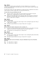
Step
1520-14
1.
Ensure
that
the
circuit
breaker
is
in
the
on
position.
2.
Using
a
multimeter,
attach
the
black
multimeter
cable
lead
to
the
return
bus
bar
(+),
and
then
attach
the
red
multimeter
cable
lead
to
the
bottom
terminal
on
the
circuit
breaker.
3.
Measure
for
-40
to
-60
V
dc
between
the
-48
V
dc
circuit
breaker
and
the
return
bus
bar
(lower
bar)
in
the
power
distribution
panel.
Is
the
voltage
between
-40
and
-60
V
dc?
NO
Replace
the
circuit
breaker.
Then
go
to
″
MAP
0410:
Repair
Checkout
″
in
the
Diagnostic
Information
for
Multiple
Bus
Systems
.
YES
Go
to
“Step
1520-15.”
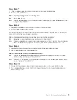
Step
1520-15
Has
the
device
power
supply
previously
been
replaced?
NO
Replace
the
power
supply.
Then
go
to
″
MAP
0410:
Repair
Checkout
″
in
the
Diagnostic
Information
for
Multiple
Bus
Systems
.
YES
Replace
the
cable.
Then
go
to
″
MAP
0410:
Repair
Checkout
″
in
the
Diagnostic
Information
for
Multiple
Bus
Systems
.
20
7014
Model
T00,
and
Model
T42
Service
Guide
Summary of Contents for THINKPAD T42 -
Page 1: ...7014 Series Model T00 and Model T42 System Rack Service Guide SA38 0577 05 ERserver...
Page 2: ......
Page 3: ...7014 Series Model T00 and Model T42 System Rack Service Guide SA38 0577 05 ERserver...
Page 10: ...viii 7014 Model T00 and Model T42 Service Guide...
Page 36: ...24 7014 Model T00 and Model T42 Service Guide...
Page 72: ...60 7014 Model T00 and Model T42 Service Guide...
Page 80: ...68 7014 Model T00 and Model T42 Service Guide...
Page 85: ......


