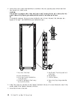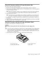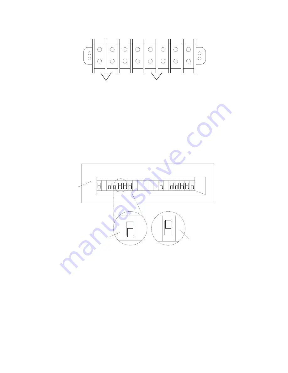
1
2
3
4
5
6
7
8
1
2
1
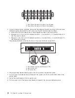
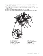
Power
Status
Connections
for
Side
A
Circuit
Breaker
2
Power
Status
Connections
for
Side
B
Circuit
Breaker
2.
Using
a
polarity-sensitive
multimeter,
ensure
that
the
voltage
and
polarity
are
correct
at
the
dc
power
distribution
panel
(check
both
the
-48
V
dc
bus
and
the
-48
V
dc
return
bus)
as
follows:
a.
Ensure
that
all
circuit
breakers
are
off
(circuit
breaker
switches
in
the
down
position).
b.
Measure
for
-40
V
dc
to
-60
V
dc
between
position
1
(-)
and
position
2
(+)
on
terminal
board
2
to
test
the
power
for
side
A.
c.
Measure
for
-40
V
dc
to
-60
V
dc
between
position
5
(-)
and
position
6
(+)
on
terminal
board
2
to
test
the
power
for
side
B.
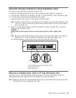
The
following
illustration
shows
the
front
view
of
the
power
distribution
panel
(PDP)
2
3
1
A1
B1
A2
B2
A3
B3
A4
B4
A5
B5
A6
B6
A7 A8 A9
B7 B8 B9
1
Circuit
Breaker
Positions
(Not
labeled
on
PDP)
2
Down
Position
(Off)
3
Up
Position
(On)
3.
Plug
all
externally
attached
device
power
cords
into
customer’s
the
electrical
outlets.
4.
Turn
on
power
to
all
external
devices
attached
to
the
system
unit.
For
more
information,
refer
to
the
service
guide.
5.
Set
all
the
circuit
breakers
to
the
on
position
(up).
6.
Turn
on
power
to
all
of
the
devices
and
drawers
connected
to
the
dc
power
distribution
panel.
28
7014
Model
T00,
and
Model
T42
Service
Guide
Summary of Contents for THINKPAD T42 -
Page 1: ...7014 Series Model T00 and Model T42 System Rack Service Guide SA38 0577 05 ERserver...
Page 2: ......
Page 3: ...7014 Series Model T00 and Model T42 System Rack Service Guide SA38 0577 05 ERserver...
Page 10: ...viii 7014 Model T00 and Model T42 Service Guide...
Page 36: ...24 7014 Model T00 and Model T42 Service Guide...
Page 72: ...60 7014 Model T00 and Model T42 Service Guide...
Page 80: ...68 7014 Model T00 and Model T42 Service Guide...
Page 85: ......


