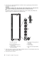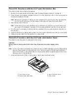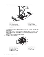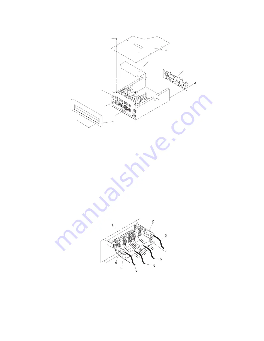
The
following
illustration
shows
a
typical
dc
power
distribution
panel
(internal
view).
1
2
9
5
8
3
4
6
7
1
Mounting
Screws
6
Front
Bezel
2
Top
Cover
7
Bezel
Mounting
Screws
3
Bus
Bar
Shield
(Insulation)
8
Circuit
Breaker
Switches
4
Terminal
Block
(Both
Sides
of
the
Rear
Cover)
9
Circuit
Breaker
Position
Labels
5
Covers
for
Empty
Circuit
Breaker
Positions
7.
With
a
multimeter,
verify
that
no
voltage
exists
between
the
two
-48
V
dc
bus
bars
and
the
two
-48
V
dc
return
bus
bars.
8.
Ensure
that
the
customer’s
service
provider
completely
disconnects
the
two
-48
V
dc
power
source
cables
from
the
-48
V
dc
bus
bars,
and
the
two
-48
V
dc
return
ground
cables
from
the
-48
V
dc
return
bus
bars.
9.
Record
the
locations
and
connection
points
of
all
cables.
10.
Disconnect
all
drawer
power
cables.
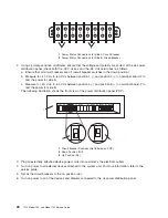
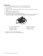
1
Front
of
Power
Distribution
Panel
6
B
Return
(-)
Power
Cable
2
A
-48
V
dc
(-)
Bus
Bar
7
B
-48
V
dc
(-)
Power
Cable
3
A
-48
V
dc
(-)
Power
Cable
8
B
Return
(-)
Bus
Bar
4
A
Return
(-)
Bus
Bar
9
B
-48
V
dc
(-)
Bus
Bar
5
A
Return
(-)
Power
Cable
32
7014
Model
T00,
and
Model
T42
Service
Guide
Summary of Contents for THINKPAD T42 -
Page 1: ...7014 Series Model T00 and Model T42 System Rack Service Guide SA38 0577 05 ERserver...
Page 2: ......
Page 3: ...7014 Series Model T00 and Model T42 System Rack Service Guide SA38 0577 05 ERserver...
Page 10: ...viii 7014 Model T00 and Model T42 Service Guide...
Page 36: ...24 7014 Model T00 and Model T42 Service Guide...
Page 72: ...60 7014 Model T00 and Model T42 Service Guide...
Page 80: ...68 7014 Model T00 and Model T42 Service Guide...
Page 85: ......

