Step 1548-23
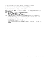
1. Ensure that the diagnostics and the operating system are shut down.
2. Turn off the power.
3. If you have not already done so, configure the service processor with the instructions in note 7 on
page 77 and then return here and continue.
4. Exit the service processor menus and remove the power cords.
5. Place the drawer into the service position and remove the service access cover.
6. Record the slot numbers of the PCI adapters. Label and record the locations of any cables attached to
the adapters. Disconnect any cables attached to the adapters and remove all the adapters.
7. Plug in the power cords and wait for the operator panel to display
OK
.
8. Turn on the power.
Does the system stop with the same error code displayed on the operator panel that directed you
to this MAP step?
NO
Go to “Step 1548-25”.
YES
Go to “Step 1548-24”.
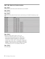
Step 1548-24
One of the FRUs remaining in the system unit is defective.
1. Turn off the power, remove the power cords and exchange the CEC backplane. See the notes on page
39.
2. Plug in the power cable and wait for the operator panel to display
OK
.
3. Turn on the power.
Does the system stop with the same error code displayed on the operator panel that directed you
to this MAP step?
NO
Go to “MAP 0410: Repair Checkout” on page 45.
YES
Reinstall the original FRU.
If the symptom did not change and all the FRUs have been exchanged, return to “Step 1548-2” on
page 78.
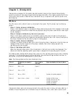
Step 1548-25
The system is working correctly with this configuration. One of the FRUs (adapters) that you removed is
probably defective.
1. Turn off the power and remove the power cable from the power outlet.
2. Install a FRU (adapter) and connect any cables and devices that were attached to it.
3. Plug in the power cable and wait for the operator panel to display
OK
.
4. Turn on the power.
5. If the Console Selection panel is displayed, choose the firmware console.
6. Enter the appropriate password if you are prompted to do so.
Does the system stop with the same error code displayed on the operator panel that directed you
to this MAP step?
NO
Repeat this step until all of the FRUs (adapters) are installed, and then go to “MAP 0410: Repair
Checkout” on page 45.
YES
Go to “Step 1548-26”.
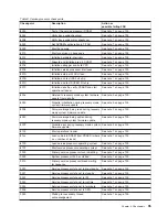
Step 1548-26
The last FRU installed or one of its attached devices is probably defective.
1. Turn off the power and remove the power cables from the power outlet.
88
NAS Gateway 500 Service Guide
Summary of Contents for TotalStorage NAS Gateway 500
Page 1: ...IBM TotalStorage NAS Gateway 500 Service Guide GY27 0418 00 ...
Page 2: ......
Page 3: ...IBM TotalStorage NAS Gateway 500 Service Guide GY27 0418 00 ...
Page 16: ...xiv NAS Gateway 500 Service Guide ...
Page 20: ...xviii NAS Gateway 500 Service Guide ...
Page 36: ...System logic flow Note Not all components are supported 16 NAS Gateway 500 Service Guide ...
Page 52: ...32 NAS Gateway 500 Service Guide ...
Page 58: ...38 NAS Gateway 500 Service Guide ...
Page 112: ...92 NAS Gateway 500 Service Guide ...
Page 266: ...246 NAS Gateway 500 Service Guide ...
Page 326: ...306 NAS Gateway 500 Service Guide ...
Page 353: ...Chapter 11 Removal and replacement procedures 333 ...
Page 392: ...372 NAS Gateway 500 Service Guide ...
Page 402: ...382 NAS Gateway 500 Service Guide ...
Page 412: ...392 NAS Gateway 500 Service Guide ...
Page 440: ...420 NAS Gateway 500 Service Guide ...
Page 446: ...426 NAS Gateway 500 Service Guide ...
Page 448: ...428 NAS Gateway 500 Service Guide ...
Page 466: ...446 NAS Gateway 500 Service Guide ...
Page 469: ......
Page 470: ... Printed in U S A GY27 0418 00 ...
Page 471: ...Spine information IBM TotalStorage NAS Gateway 500 NAS Gateway 500 Service Guide GY27 0418 00 ...


