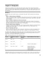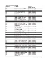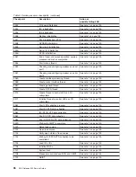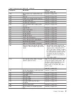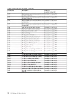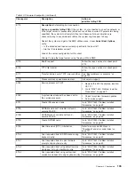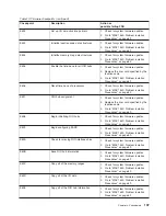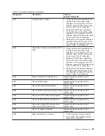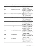
Table 10. Firmware checkpoints (continued)
Checkpoint
Description
Action or
possible failing FRU
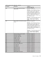
E174
Description:
Establishing host connection
Action or possible failing FRU:
If the system is not connected to an active network, or
if the target server is inaccessible (which can result from incorrect IP parameters being
specified), the system still attempts to boot and because time-out durations are
necessarily long to accommodate retries, the system might appear to hang.
Restart the system and get to the SMS utilities menu. Under
Select Boot Options
,
verify:
v
Is the intended boot device correctly specified in the boot list?
v
Are the IP parameters correct?
Look at the server configuration for this client.
Attempt to ping the target server using the ping utility in SMS.
E175
BootP request
Follow the repair actions for checkpoint
E174.
E176
TFTP file transfer
Follow the repair actions for checkpoint
E174.
E177
Transfer failure due to TFTP error condition
See “Boot problems or concerns” on
page 122.
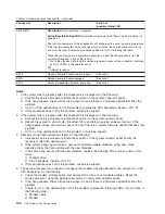
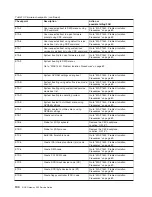
E17B
Processor clock speed measurement
Call service support.
E183
Service processor POST
1. Replace the CEC backplane, location:
U0.1-P1.
2. Go to “MAP 1540: Problem Isolation
Procedures” on page 69.
E18D
A system reset request has been sent to
the service processor.
1. Check for system firmware updates.
2. Call service support.
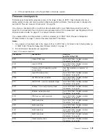
E191
Create ISA reserved node
Go to “MAP 1540: Problem Isolation
Procedures” on page 69.
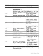
E19A
NVRAM auto-boot? variable not found -
assume FALSE
Go to “MAP 1540: Problem Isolation
Procedures” on page 69.
E19B
NVRAM menu? variable not found -
assume FALSE
Go to “MAP 1540: Problem Isolation
Procedures” on page 69.
E19D
Create NVRAM node
Go to “MAP 1540: Problem Isolation
Procedures” on page 69.
E19E
Real-time clock (RTC) initialization
Refer to error code 28030xxx in
“Checkpoint and error code index” on
page 127.
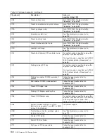
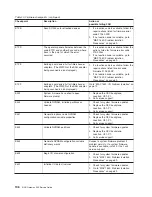
E1A0
User requested boot to SMS menus using
keyboard entry
Go to “MAP 1540: Problem Isolation
Procedures” on page 69.
E1A1
User requested boot to open firmware
prompt using keyboard entry
Go to “MAP 1540: Problem Isolation
Procedures” on page 69.
E1A2
User requested boot using default service
mode boot list using keyboard entry
Go to “MAP 1540: Problem Isolation
Procedures” on page 69.
E1A3
User requested boot using customized
service mode boot list using keyboard entry
Go to “MAP 1540: Problem Isolation
Procedures” on page 69.
Chapter 4. Checkpoints
103
Summary of Contents for TotalStorage NAS Gateway 500
Page 1: ...IBM TotalStorage NAS Gateway 500 Service Guide GY27 0418 00 ...
Page 2: ......
Page 3: ...IBM TotalStorage NAS Gateway 500 Service Guide GY27 0418 00 ...
Page 16: ...xiv NAS Gateway 500 Service Guide ...
Page 20: ...xviii NAS Gateway 500 Service Guide ...
Page 36: ...System logic flow Note Not all components are supported 16 NAS Gateway 500 Service Guide ...
Page 52: ...32 NAS Gateway 500 Service Guide ...
Page 58: ...38 NAS Gateway 500 Service Guide ...
Page 112: ...92 NAS Gateway 500 Service Guide ...
Page 266: ...246 NAS Gateway 500 Service Guide ...
Page 326: ...306 NAS Gateway 500 Service Guide ...
Page 353: ...Chapter 11 Removal and replacement procedures 333 ...
Page 392: ...372 NAS Gateway 500 Service Guide ...
Page 402: ...382 NAS Gateway 500 Service Guide ...
Page 412: ...392 NAS Gateway 500 Service Guide ...
Page 440: ...420 NAS Gateway 500 Service Guide ...
Page 446: ...426 NAS Gateway 500 Service Guide ...
Page 448: ...428 NAS Gateway 500 Service Guide ...
Page 466: ...446 NAS Gateway 500 Service Guide ...
Page 469: ......
Page 470: ... Printed in U S A GY27 0418 00 ...
Page 471: ...Spine information IBM TotalStorage NAS Gateway 500 NAS Gateway 500 Service Guide GY27 0418 00 ...

