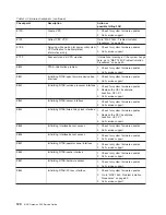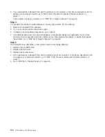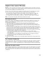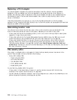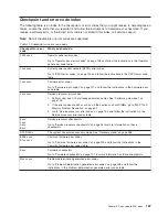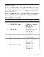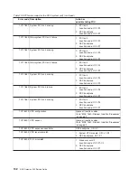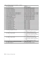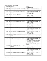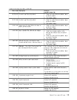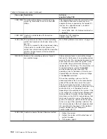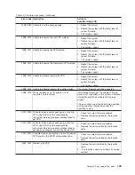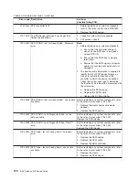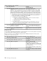
Table 13. SPCN error codes for the CEC (system unit) (continued)
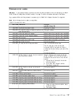
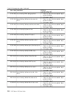
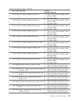
Error code Description
Action or
possible failing FRU
1011 9280 SPCN interface failure
1. Check for system firmware updates. Apply
the update if it is available.
2. Replace the system backplane, location:
U0.1-P1.
1011 9281 SPCN interface failure
1. Check for system firmware updates. Apply
the update if it is available.
2. Replace the system backplane, location:
U0.1-P1.
1011 9282 SPCN interface failure
1. Check for system firmware updates. Apply
the update if it is available.
2. Replace the system backplane, location:
U0.1-P1.
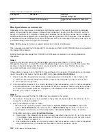
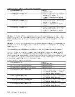
Attention:
If you replace FRUs or perform an action on an I/O subsystem and the problem is still not
corrected, go to “MAP 1542: I/O Problem Isolation” on page 72 unless you were already directed to any
MAP 154
x
by the error code. Otherwise, call support if the actions for an error code do not resolve the
problem.
Attention:
If the error code that brought you to this chapter originated in the operating system error log,
please be aware that an error might require an additional 15 minutes to be propagated to the operating
system error log.
If you replace FRUs and the problem is corrected, go to “MAP 0410: Repair Checkout” on page 45.
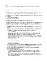
The “nn” in “1nn1 xxxx”, where nn is between 2 and 3F hexadecimal, inclusive, is replaced by the I/O
subsystem drawer number (in hexadecimal) in the error code that is reported by the system. The I/O
drawer number in the location code of a failing FRU will be converted to decimal (which is shown as U0.dd
in the following table). The “dd” value ranges from 02 to 63, inclusive. For example, the error code 11F1
1510 will have location codes U0.31-V1 and U0.31-P1 listed.
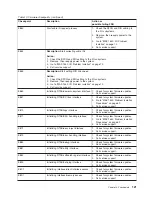
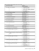
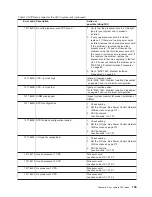
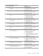
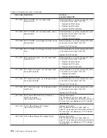
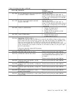
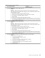
Table 14. SPCN error codes for I/O subsystems
Error code Description
Action or
possible failing FRU
1nn1 00AC AC loss or brownout detected.
Informational message.
1nn1 00EF Remote emergency power off occurred.
Informational message.
1nn1 1510 Power supply 1 source failure
1. Check the input voltage to the power supply.
2. I/O subsystem power supply 1, U0.dd-V1.
3. I/O subsystem backplane, U0.dd-P1.
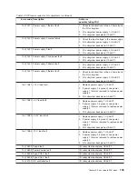
1nn1 1511 Power supply 1 fault
1. I/O subsystem power supply 1, U0.dd-V1.
2. I/O subsystem backplane, U0.dd-P1.
1nn1 1512 Power supply 1 non-power fault
1. I/O subsystem power supply 1, U0.dd-V1.
2. I/O subsystem backplane, U0.dd-P1.
1nn1 1513 Power supply 1 domain fault
1. I/O subsystem power supply 1, U0.dd-V1.
2. I/O subsystem backplane, U0.dd-P1.
134
NAS Gateway 500 Service Guide
Summary of Contents for TotalStorage NAS Gateway 500
Page 1: ...IBM TotalStorage NAS Gateway 500 Service Guide GY27 0418 00 ...
Page 2: ......
Page 3: ...IBM TotalStorage NAS Gateway 500 Service Guide GY27 0418 00 ...
Page 16: ...xiv NAS Gateway 500 Service Guide ...
Page 20: ...xviii NAS Gateway 500 Service Guide ...
Page 36: ...System logic flow Note Not all components are supported 16 NAS Gateway 500 Service Guide ...
Page 52: ...32 NAS Gateway 500 Service Guide ...
Page 58: ...38 NAS Gateway 500 Service Guide ...
Page 112: ...92 NAS Gateway 500 Service Guide ...
Page 266: ...246 NAS Gateway 500 Service Guide ...
Page 326: ...306 NAS Gateway 500 Service Guide ...
Page 353: ...Chapter 11 Removal and replacement procedures 333 ...
Page 392: ...372 NAS Gateway 500 Service Guide ...
Page 402: ...382 NAS Gateway 500 Service Guide ...
Page 412: ...392 NAS Gateway 500 Service Guide ...
Page 440: ...420 NAS Gateway 500 Service Guide ...
Page 446: ...426 NAS Gateway 500 Service Guide ...
Page 448: ...428 NAS Gateway 500 Service Guide ...
Page 466: ...446 NAS Gateway 500 Service Guide ...
Page 469: ......
Page 470: ... Printed in U S A GY27 0418 00 ...
Page 471: ...Spine information IBM TotalStorage NAS Gateway 500 NAS Gateway 500 Service Guide GY27 0418 00 ...

