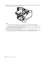
5. After you shut down the operating system, set the power switches of any attached devices to Off.
6.
If necessary, disconnect the power sources to both of the NAS Gateway 500’s power supplies.
Starting the system
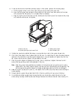
To power on the system, perform the following steps in sequence.
1. Open the front rack door.
2. If they were disconnected, reconnect both power sources to the system.
3. Before you press the power button on your operator panel, observe the following:
v
The power LED is slowly blinking.
v
An
OK
prompt is visible in the operator panel.
4. Press the power-on button on the operator panel.
After pressing the power button located on the operator panel, observe the following:
a. The power LED begins to blink visibly faster.
b. The system cooling fans are activated and begin to accelerate up to operating speed.
Note:
There is approximately a 40-second transition period between the time the power button is
pressed and the power LED remains on solid (no longer blinking).
c. The power LED stays on solid and progress indicators, also referred to as
checkpoints
, are visible
on the operator panel.
2
9
8
7
OK
6
1
3 4
5
R
1
Power-on button
6
Operator panel display
2
Power LED
7
(FS1) front serial connector (RJ-48 connector)
3
Attention LED
8
Service processor reset switch (pinhole)
4
SCSI port activity
9
System reset button
5
Ethernet port activity
Note:
The boot process can take 15-30 minutes, depending on the system configuration and
attachments. Approximately 30 seconds after the boot process has completed, the operator
panel will go blank (unless this is the very first boot before initial configuration is complete;
then the IP address for Ethernet port 1 is displayed). At this point, you can ping or telnet into
the machine. If a console is attached to serial port 1, the POST messages and checkpoints
are displayed on the console, and, when boot is complete, the login: prompt displays.
Messages might continue to display after the login prompt.
5. If you are clustering, you need to bring this node back into the cluster pair to resume file serving using
the hostname and group name recorded at shutdown.
a. Log in to the system as root user.
b. Rejoin the cluster by typing on the command line:
/opt/nas/bin/clnasrennode -n
<hostname>
c. Poll status until the node has finished stabilizing:
/opt/nas/bin/clnasnodestate -n
<hostname>
d. Once the status changes to “stable,” relocate the volumes back to this node for file serving:
/opt/nas/bin/clnasrelocate -g
<groupname>
-n
<hostname>
Chapter 11. Removal and replacement procedures
311
Summary of Contents for TotalStorage NAS Gateway 500
Page 1: ...IBM TotalStorage NAS Gateway 500 Service Guide GY27 0418 00 ...
Page 2: ......
Page 3: ...IBM TotalStorage NAS Gateway 500 Service Guide GY27 0418 00 ...
Page 16: ...xiv NAS Gateway 500 Service Guide ...
Page 20: ...xviii NAS Gateway 500 Service Guide ...
Page 36: ...System logic flow Note Not all components are supported 16 NAS Gateway 500 Service Guide ...
Page 52: ...32 NAS Gateway 500 Service Guide ...
Page 58: ...38 NAS Gateway 500 Service Guide ...
Page 112: ...92 NAS Gateway 500 Service Guide ...
Page 266: ...246 NAS Gateway 500 Service Guide ...
Page 326: ...306 NAS Gateway 500 Service Guide ...
Page 353: ...Chapter 11 Removal and replacement procedures 333 ...
Page 392: ...372 NAS Gateway 500 Service Guide ...
Page 402: ...382 NAS Gateway 500 Service Guide ...
Page 412: ...392 NAS Gateway 500 Service Guide ...
Page 440: ...420 NAS Gateway 500 Service Guide ...
Page 446: ...426 NAS Gateway 500 Service Guide ...
Page 448: ...428 NAS Gateway 500 Service Guide ...
Page 466: ...446 NAS Gateway 500 Service Guide ...
Page 469: ......
Page 470: ... Printed in U S A GY27 0418 00 ...
Page 471: ...Spine information IBM TotalStorage NAS Gateway 500 NAS Gateway 500 Service Guide GY27 0418 00 ...


