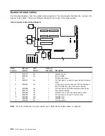
Table 21. LEDs visible from the back of the NAS Gateway 500 (continued)
Location
Name
Color
Notes
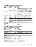
Third LED from the
right below RIO
connector 1
Ethernet 2
connector mode
indicator
Green
10 Mbps – Off
100 Mbps – On
Fourth LED from the
right below RIO
connector 1
Ethernet 2
connector activity
indicator
Green
On – Receiving information
Off – Not receiving information
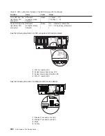
See the following illustration for RIO connector LED location details.
1 2 3
4
1
RIO-G 0 identify LED
2
System drawer back power LED
3
System drawer back attention LED
4
RIO-G 1 identify LED
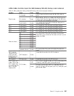
See the following illustration for Ethernet LED location details.
1
1
2
2
3
3
4
4
1
Ethernet 1 connector and LED
2
Ethernet 2 connector and LED
3
Mode
4
Activity
386
NAS Gateway 500 Service Guide
Summary of Contents for TotalStorage NAS Gateway 500
Page 1: ...IBM TotalStorage NAS Gateway 500 Service Guide GY27 0418 00 ...
Page 2: ......
Page 3: ...IBM TotalStorage NAS Gateway 500 Service Guide GY27 0418 00 ...
Page 16: ...xiv NAS Gateway 500 Service Guide ...
Page 20: ...xviii NAS Gateway 500 Service Guide ...
Page 36: ...System logic flow Note Not all components are supported 16 NAS Gateway 500 Service Guide ...
Page 52: ...32 NAS Gateway 500 Service Guide ...
Page 58: ...38 NAS Gateway 500 Service Guide ...
Page 112: ...92 NAS Gateway 500 Service Guide ...
Page 266: ...246 NAS Gateway 500 Service Guide ...
Page 326: ...306 NAS Gateway 500 Service Guide ...
Page 353: ...Chapter 11 Removal and replacement procedures 333 ...
Page 392: ...372 NAS Gateway 500 Service Guide ...
Page 402: ...382 NAS Gateway 500 Service Guide ...
Page 412: ...392 NAS Gateway 500 Service Guide ...
Page 440: ...420 NAS Gateway 500 Service Guide ...
Page 446: ...426 NAS Gateway 500 Service Guide ...
Page 448: ...428 NAS Gateway 500 Service Guide ...
Page 466: ...446 NAS Gateway 500 Service Guide ...
Page 469: ......
Page 470: ... Printed in U S A GY27 0418 00 ...
Page 471: ...Spine information IBM TotalStorage NAS Gateway 500 NAS Gateway 500 Service Guide GY27 0418 00 ...


