Note:
The modem initialization strings provided are on an AS IS basis. Although they have been tested in
a typical AIX environment they might have to be modified depending on the actual setup and
configuration of your environment.
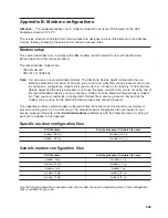
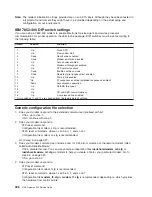
IBM 7852-400 DIP switch settings
If you are using a 7852-400 modem to enable Electronic Service Agent and service processor
communications, for proper operation, the dual in-line package (DIP) switches must be set according to
the following table:
Switch
Position
Function
1
Up
Force DTR
2
Up
Flow control &E4
3
Down
Result codes enabled
4
Down
Modem emulation disabled
5
Up
Auto answer enabled
6
Up
Maximum throughput enabled
7
Up
RTS normal functions
8
Down
Enable command mode
9
Down
Remote digital loopback test enabled
10
Up
Dial-up line enabled
11
*Up
AT responses enabled (extended responses disabled)
12
*Down
Asynchronous operation
13
Up
28.8-KB line speed
14
Up
15
Up
CD and DSR normal functions
16
Up
2-wire leased line enabled
* Only switches 11 and 12 are changed from the factory default settings.
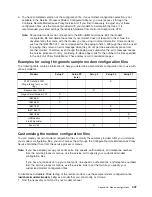
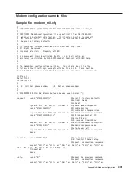
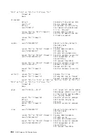
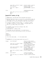
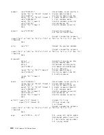
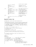
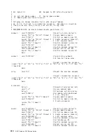
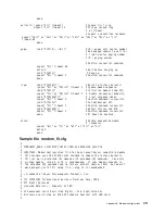
Generic configuration file selection
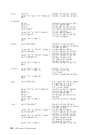
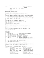
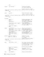
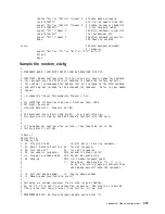
1. Does your modem respond to the extended command set (prefixed with &)?
v
If Yes, go to step 3.
v
If No, continue with step 2.
2. Does your modem respond to:
v
ATZ reset command.
Configuration file modem_z.cfg is recommended.
v
ATZn reset commands, where n can be 0, 1, and so on?
Configuration file modem_z0.cfg is recommended.
Go to step 5 on page 397.
3. Does your modem command set include a test for V.42 error correction at the remote modem (often
called Auto-Reliable Mode)?
v
If Yes, disable this test. You can use sample configuration files
/usr/share/modem_m0.cfg
or
/usr/share/modem_m1.cfg
as models to help you create a file for your particular modem. Go to
step 5.5 on page 397.
v
If No, go to step 4.
4. Does your modem respond to:
v
ATZ reset command.
Configuration file modem_f.cfg is recommended.
v
ATZ
n
reset commands, where n can be 0, 1, and so on?
Configuration file
modem_f0.cfg
or
modem_f1.cfg
is recommended, depending on which provides
the hardware flow control profile.
396
NAS Gateway 500 Service Guide
Summary of Contents for TotalStorage NAS Gateway 500
Page 1: ...IBM TotalStorage NAS Gateway 500 Service Guide GY27 0418 00 ...
Page 2: ......
Page 3: ...IBM TotalStorage NAS Gateway 500 Service Guide GY27 0418 00 ...
Page 16: ...xiv NAS Gateway 500 Service Guide ...
Page 20: ...xviii NAS Gateway 500 Service Guide ...
Page 36: ...System logic flow Note Not all components are supported 16 NAS Gateway 500 Service Guide ...
Page 52: ...32 NAS Gateway 500 Service Guide ...
Page 58: ...38 NAS Gateway 500 Service Guide ...
Page 112: ...92 NAS Gateway 500 Service Guide ...
Page 266: ...246 NAS Gateway 500 Service Guide ...
Page 326: ...306 NAS Gateway 500 Service Guide ...
Page 353: ...Chapter 11 Removal and replacement procedures 333 ...
Page 392: ...372 NAS Gateway 500 Service Guide ...
Page 402: ...382 NAS Gateway 500 Service Guide ...
Page 412: ...392 NAS Gateway 500 Service Guide ...
Page 440: ...420 NAS Gateway 500 Service Guide ...
Page 446: ...426 NAS Gateway 500 Service Guide ...
Page 448: ...428 NAS Gateway 500 Service Guide ...
Page 466: ...446 NAS Gateway 500 Service Guide ...
Page 469: ......
Page 470: ... Printed in U S A GY27 0418 00 ...
Page 471: ...Spine information IBM TotalStorage NAS Gateway 500 NAS Gateway 500 Service Guide GY27 0418 00 ...


