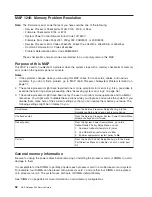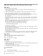
Attention:
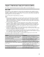
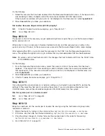
Go to the service processor menus. In the System Information Menu, select
Memory
Configuration/ Deconfiguration
. Verify on the first panel that memory repeat gard is disabled. If it is
enabled, disable it for the duration of this MAP. When exiting this MAP to go to MAP 0410 in the
RS/6000
Eserver
pSeries Diagnostic Information for Multiple Bus Systems
; also return the setting to enabled if
necessary.
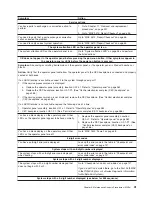
Step 1240-1
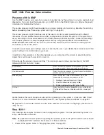
1. Record the error code that sent you to this map.
2. Go to the service processor menus and disable memory repeat gard if it is not already disabled.
3. Turn off the power. Remove the power cords.
4. Remove and reinstall the processor cards.
5. Reattach the power cords. Wait for
OK
to display in the operator panel.
6. Turn on the power. Attempt to boot to the SMS menus. (The system might stop with an 8-digit error
code before it reaches the SMS menus.)
7. Power off the system using the white power button. After
OK
is displayed in the operator panel, look at
the memory configuration/deconfiguration menu.
Are any DIMMs deconfigured or does the error code recorded earlier in this step still appear?
No
Reseating the processor cards has corrected the problem.
Enable memory repeat gard if necessary.
Go to “MAP 0410: Repair Checkout” on page 45.
Yes
If there is only 1 processor card installed, tag it as “suspect bad” and go to “Step 1240-6” on
page 54. If there are 2 processor cards installed, go to “Step 1240-2”.
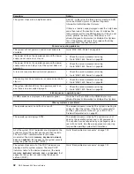
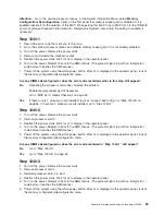
Step 1240-2
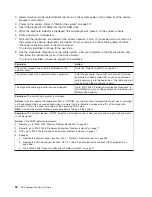
1. Turn off the power. Remove the power cords.
2. Remove processor card 2.
3. Reattach the power cords. Wait for
OK
to display in the operator panel.
4. Turn on the power. Attempt to boot to the SMS menus. (The system might stop with an 8-digit error
code before it reaches the SMS menus.)
5. Power off the system using the white power button. After
OK
is displayed in the operator panel, look at
the memory configuration/deconfiguration menu.
Are any DIMMs deconfigured or does the error code recorded in “Step 1240-1” still appear?
No
Go to “Step 1240-3”.
Yes
Go to “Step 1240-6” on page 54.
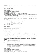
Step 1240-3
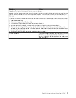
1. Turn off the power. Remove the power cords.
2. Remove processor card 1.
3. Reinstall processor card 2 in slot 1.
4. Reattach the power cords. Wait for
OK
to display in the operator panel.
5. Turn on the power. Attempt to boot to the SMS menus. (The system might stop with an 8-digit error
code before it reaches the SMS menus.)
6. Power off the system using the white power button. After
OK
is displayed in the operator panel, look at
the memory configuration/deconfiguration menu.
Chapter 3. Maintenance Analysis Procedures (MAPs)
53
Summary of Contents for TotalStorage NAS Gateway 500
Page 1: ...IBM TotalStorage NAS Gateway 500 Service Guide GY27 0418 00 ...
Page 2: ......
Page 3: ...IBM TotalStorage NAS Gateway 500 Service Guide GY27 0418 00 ...
Page 16: ...xiv NAS Gateway 500 Service Guide ...
Page 20: ...xviii NAS Gateway 500 Service Guide ...
Page 36: ...System logic flow Note Not all components are supported 16 NAS Gateway 500 Service Guide ...
Page 52: ...32 NAS Gateway 500 Service Guide ...
Page 58: ...38 NAS Gateway 500 Service Guide ...
Page 112: ...92 NAS Gateway 500 Service Guide ...
Page 266: ...246 NAS Gateway 500 Service Guide ...
Page 326: ...306 NAS Gateway 500 Service Guide ...
Page 353: ...Chapter 11 Removal and replacement procedures 333 ...
Page 392: ...372 NAS Gateway 500 Service Guide ...
Page 402: ...382 NAS Gateway 500 Service Guide ...
Page 412: ...392 NAS Gateway 500 Service Guide ...
Page 440: ...420 NAS Gateway 500 Service Guide ...
Page 446: ...426 NAS Gateway 500 Service Guide ...
Page 448: ...428 NAS Gateway 500 Service Guide ...
Page 466: ...446 NAS Gateway 500 Service Guide ...
Page 469: ......
Page 470: ... Printed in U S A GY27 0418 00 ...
Page 471: ...Spine information IBM TotalStorage NAS Gateway 500 NAS Gateway 500 Service Guide GY27 0418 00 ...

