background image

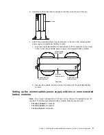
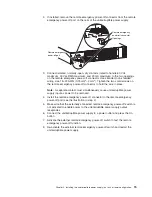
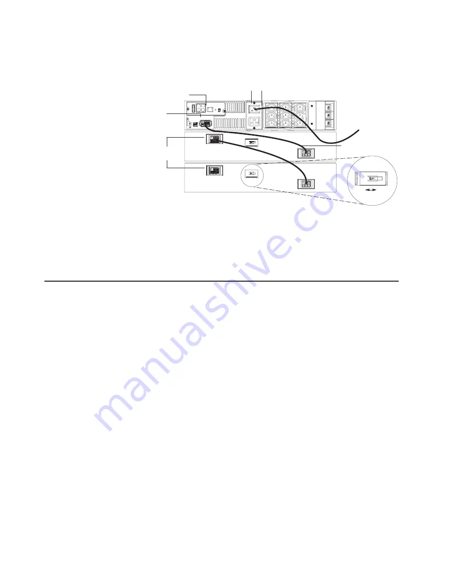
To


connect


the


uninterruptible


power


supply


to


the


extended


battery


modules,


complete


the


following


steps:


1.


Make


sure


that


all


battery


circuit


breakers


on


the


extended


battery


modules


are


in


the


Off


position.


Battery circuit breaker

UPS battery
connector

Power cord

Web/SNMP card

Input connector

On

Off

Extended battery
module cable

Extended battery
module connectors

1 2

Off

On


2.


Connect


an


extended


battery


module


to


the


uninterruptible


power


supply


using


an


extended


battery


module


cable


(see


the


illustration


in


step


1).


Connect


one


end


of


the


extended


battery


module


cable


to


an


extended


battery


module


connector


and


then


connect


the


other


end


to


the


uninterruptible


power


supply


battery


connector.


Crossing


the


cable


as


shown


in


the


illustration


is


the


preferred


method.

Connecting


the


uninterruptible


power


supply


to


the


extended


battery


modules


(tower


configuration)


The


illustration


in


this


section


shows


a


typical


installation


with


a


UPS3000


LV.


See


“Rear


view”


on


page


18


for


the


rear


view


of


the


UPS3000


HV


model.


To


connect


the


uninterruptible


power


supply


to


the


extended


battery


modules,


complete


the


following


steps:


1.


Make


sure


that


all


battery


circuit


breakers


on


the


extended


battery


modules


are


in


the


Off


position.


12


UPS


3000


LV


and


UPS3000


HV:


Installation


and


Maintenance


Guide

Summary of Contents for UPS3000 HV

Page 1: ...UPS3000 LV and UPS3000 HV Installation and Maintenance Guide ...

Page 2: ......

Page 3: ...UPS3000 LV and UPS3000 HV Installation and Maintenance Guide ...

Page 4: ...nt of Limited Warranty Z125 4753 08 04 2004 on page 45 and Appendix C Notices on page 63 First Edition April 2006 Copyright International Business Machines Corporation 2006 All rights reserved US Government Users Restricted Rights Use duplication or disclosure restricted by GSA ADP Schedule Contract with IBM Corp ...

Page 5: ...alleert eerst de veiligheidsvoorschriften Ennen kuin asennat tämän tuotteen lue turvaohjeet kohdasta Safety Information Avant d installer ce produit lisez les consignes de sécurité Vor der Installation dieses Produkts die Sicherheitshinweise lesen Prima di installare questo prodotto leggere le Informazioni sulla Sicurezza Les sikkerhetsinformasjonen Safety Information før du installerer dette prod...

Page 6: ...he caution or danger statement in the IBM ERserver Safety Notices document For example if a caution statement ends with a number D005 translations for that caution statement appear in the IBM ERserver Safety Notices document under D005 Be sure to read all caution and danger statements in this documentation before performing the instructions Read any additional safety information that comes with yo...

Page 7: ...ables v Never turn on any equipment when there is evidence of fire water or structural damage v Disconnect the attached power cords telecommunications systems networks and modems before you open the device covers unless instructed otherwise in the installation and configuration procedures v Connect and disconnect cables as described below when installing moving or opening covers on this product or...

Page 8: ...ulations In the United States IBM has a process for the collection of this battery For information call 1 800 426 4333 Have the IBM part number for the battery unit available when you call C004 CAUTION or 32 kg 70 5 lb or 32 55 kg 70 5 121 2 lb The weight of this part or unit is between 32 and 55 kg 70 5 and 121 2 lb It takes three persons to safely lift this part or unit C010 DANGER Hazardous vol...

Page 9: ...the outlet is correctly wired and grounded to prevent an electrical shock CAUTION v Do not install a unit in a rack where the internal rack ambient temperatures will exceed the manufacturer s recommended ambient temperature for all your rack mounted devices v Do not install a unit in a rack where the air flow is compromised Ensure that air flow is not blocked or reduced on any side front or back o...

Page 10: ...r handling ADVERTENCIA El contacto con el cable de este producto o con cables de accesorios que se venden junto con este producto pueden exponerle al plomo un elemento químico que en el estado de California de los Estados Unidos está considerado como un causante de cancer y de defectos congénitos además de otros riesgos reproductivos Lávese las manos después de usar el producto viii UPS 3000 LV an...

Page 11: ...rruptible power supply to the extended battery modules tower configuration 12 Completing the installation 13 Remote emergency power off installation 14 Chapter 3 Uninterruptible power supply controls LEDs operating modes and power 17 Front view 17 Rear view 18 Operating modes 18 Normal mode 19 Battery mode 19 Bypass mode 19 Standby mode 19 Configuration mode 20 Turning on the uninterruptible power...

Page 12: ...y conditions 39 Silencing an audible alarm 39 Troubleshooting guide 39 Appendix A Getting help and technical assistance 43 Before you call 43 Using the documentation 43 Getting help and information from the World Wide Web 44 Software service and support 44 Hardware service and support 44 Appendix B IBM Statement of Limited Warranty Z125 4753 08 04 2004 45 Part 1 General Terms 45 Part 2 Country uni...

Page 13: ... power supply documentation To check for updates go to http www ibm com support For firmware updates click Downloads and drivers For documentation updates under Search technical support type 2130 and click Search Note Changes are made periodically to the IBM Web site Procedures for locating firmware and documentation might vary slightly from what is described in this document The uninterruptible p...

Page 14: ...d from the mnt cdrom directory sh runlinux sh Select your uninterruptible power supply from the Product menu The Available Topics list displays all the documents for your uninterruptible power supply Some documents might be in folders A plus sign indicates each folder or document that has additional documents under it Click the plus sign to display the additional documents When you select a docume...

Page 15: ... amps Input voltage range for main operations 90 to 144 V 160 to 288 V Input voltage adjustable range for main operations 77 to 152 V 154 to 288 V Nominal output voltage 120 V 220 V configurable for 200 220 230 or 240 V Input frequency 50 60 Hz 4 Hz auto sensing 50 60 Hz 4 Hz auto sensing Rated power output 2880 VA 3000 VA Output power capacity in watts 2700 W 2700 W Circuit breakers Three supplem...

Page 16: ...convenient or problem situations v Attention These notices indicate potential damage to programs devices or data An attention notice is placed just before the instruction or situation in which damage could occur v Caution These statements indicate situations that can be potentially hazardous to you A caution statement is placed just before the description of a potentially hazardous procedure step ...

Page 17: ...blade screwdriver Inventory checklist The uninterruptible power supply option comes with the following items Note Your uninterruptible power supply model might not come with all of the items in the following list v Uninterruptible power supply v One bezel v Rail kit including rails and rack mounting brackets v Tower conversion kit including mounting pedestals v Documentation CD v Power management ...

Page 18: ...uninterruptible power supply with no extended battery module on page 7 v For two chassis Install two pedestals on each chassis and two extended battery module brackets see Setting up the uninterruptible power supply with an extended battery module on page 8 v For three chassis Install four extended battery module brackets see Setting up the uninterruptible power supply with two or more extended ba...

Page 19: ...ide of the uninterruptible power supply Mounting bracket 2 Place the uninterruptible power supply chassis horizontally so that the left side of the unit is accessible see the illustration in step 3 3 Position one set of two pedestals at the rear end of the chassis and one set of two pedestals at the front end of the chassis Align the holes and secure the pedestals with the 6 32 x 3 8 inch flat hea...

Page 20: ...is horizontally so that the left end of the unit is accessible see the illustration in step 3 3 Position two of the pedestals over the edge of the chassis so that the weight of the unit is evenly distributed Secure the pedestals with the 6 32 x 3 8 flat head screws that come in the accessory kit 4 Place the extended battery module chassis upside down so that the right side of the unit is accessibl...

Page 21: ...Extended battery module Uninterruptible power supply Extended battery module bracket Top view b Secure the brackets with the screws that come with the extended battery module Setting up the uninterruptible power supply with two or more extended battery modules Note For a tower configuration with three or more chassis the pedestals are not required The following extended battery module brackets are...

Page 22: ...is connected together c Secure the brackets with the screws that come with the extended battery module Connecting the internal battery Important v Check the battery recharge date on the shipping carton label If the date has expired and the batteries were never recharged do not use the uninterruptible power supply Contact your service representative v Connect the internal battery after you install ...

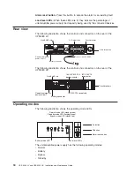
Page 23: ...ternal battery Connecting the uninterruptible power supply to the extended battery modules rack configuration The illustration in this section shows a typical installation with a UPS3000 HV See Rear view on page 18 for the rear view of the UPS3000 LV model Note You can connect up to four extended battery modules to the uninterruptible power supply If there are two uninterruptible power supplies in...

Page 24: ...e extended battery module cable to an extended battery module connector and then connect the other end to the uninterruptible power supply battery connector Crossing the cable as shown in the illustration is the preferred method Connecting the uninterruptible power supply to the extended battery modules tower configuration The illustration in this section shows a typical installation with a UPS300...

Page 25: ... communication cable that comes with the uninterruptible power supply 2 Connect the devices that you want to protect into the applicable uninterruptible power supply output receptacles For information about load segments see Load segments on page 22 Note Do not protect laser printers with the uninterruptible power supply because of the exceptionally high power requirements of the heating elements ...

Page 26: ... feature shuts down the connected devices immediately and does not follow the orderly shutdown procedure initiated by any power management software Any devices that are operating on battery power are also shut down immediately When the remote emergency power off switch is reset the connected devices will not return to battery power until the uninterruptible power supply is restarted manually If th...

Page 27: ... A separate contact must simultaneously cause uninterruptible power supply input ac power to be removed 4 Install the remote emergency power off connector in the remote emergency power off port see the illustration in step 2 5 Make sure that the externally connected remote emergency power off switch is not activated to enable power to the uninterruptible power supply output receptacles 6 Connect t...

Page 28: ...16 UPS 3000 LV and UPS3000 HV Installation and Maintenance Guide ...

Page 29: ...p the battery is recharging On battery LED When this LED is lit the uninterruptible power supply is running on battery power When this LED is flashing the battery capacity is low Battery service LED When this LED is red and flashing the battery is not connected correctly or the battery needs to be replaced Site wiring fault LED When this LED is red and flashing there are problems with the wiring o...

Page 30: ...2 Off On The following illustration shows the controls and connectors on the rear of the UPS3000 HV Remote emergency power off port IEC 320 C19 receptacle Battery connector 16A IEC 320 C20 input connector IEC 320 C13 receptacles Circuit breakers Web SNMP card 1 2 Off On Operating modes The following illustration shows the operating mode LEDs On button Off button Alarm reset button Normal mode LED ...

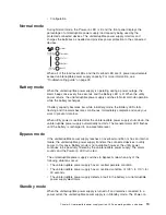
Page 31: ...en utility power is restored after the uninterruptible power supply shuts down the uninterruptible power supply automatically restarts The General alarm LED flashes until the battery is recharged to an acceptable level Bypass mode If the uninterruptible power supply reaches an overload condition or has an internal failure the uninterruptible power supply transfers the connected devices to utility ...

Page 32: ...guration mode complete the following steps 1 Press and hold the On button and the Alarm reset button simultaneously for one beep approximately five seconds The uninterruptible power supply switches to Configuration mode The LEDs flash briefly and then display the enabled options 2 Press the On button to scroll through the options Each time you press the button the uninterruptible power supply beep...

Page 33: ...ns is selected 120 230V nominal input voltage On Selecting this option changes the nominal input voltage on low voltage models to 120V and to 230V for high voltage models Flashing 120 230V is disabled one of the other input voltage options is selected 127 240V nominal input voltage On Selecting this option changes the nominal input voltage on low voltage models to 127V and to 240V for high voltage...

Page 34: ...or shutdown 2 Press and hold the Off button until the long beep ceases approximately five seconds The Power on LED starts flashing and the uninterruptible power supply switches to Standby mode if utility power is available and removes power from the connected devices 3 Disconnect the power cord from the uninterruptible power supply If you do not disconnect the uninterruptible power supply it remai...

Page 35: ...illustration shows the three load segments in the UPS3000 HV uninterruptible power supply Load segment 2 Load segment 3 Load segment 1 Chapter 3 Uninterruptible power supply controls LEDs operating modes and power 23 ...

Page 36: ...24 UPS 3000 LV and UPS3000 HV Installation and Maintenance Guide ...

Page 37: ...ptible power supply protected computer systems NetWatch client software that is used with the card comes on the Powerware Software Suite CD or at http www powerware com The client software is available for the following operating systems v Microsoft Windows 95 98 ME NT and XP v Macintosh OS X v Novell NetWare v UNIX v Linux The operating systems in the previous list communicate through TCP IP with...

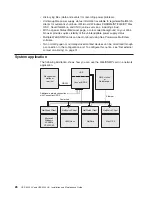
Page 38: ...g free Powerware MultiView software v Two normally open or normally closed contact devices can be monitored through a connection to the configuration port To configure this option see Set external contact monitoring on page 31 System application The following illustration shows how you can use the Web SNMP card in a network application Ethernet RS 232 UPS ConnectUPS X NMS station or Web browser Po...

Page 39: ...ninterruptible power supply power is low no power to the Web SNMP card Flashing approximately once per second Flashing approximately once per second No connection to uninterruptible power supply alternate flashing as the Web SNMP card restarts Configuring the Web SNMP card locally Use the procedure in this section to access the Web SNMP configuration utility through a serial connector Before you b...

Page 40: ...he serial line is set to 9600 baud no parity 8 data bits 1 stop bit and no flow control v If the serial line settings are correct check the cabling to be sure that all connections are secure v Make sure that the terminal program is on the correct communication port for the serial connection v Make sure that the Web SNMP card has power one or more LEDs on the card is lit and that the uninterruptibl...

Page 41: ...urn to the Main Menu 5 Type 0 to exit the Web SNMP Card Configuration Utility The Web SNMP card automatically saves all settings after exiting the configuration utility Notes 1 The Web SNMP card can take up to two minutes to establish communication with the uninterruptible power supply Wait before attempting communication with the card from a Web browser or network management system NMS 2 For Teln...

Page 42: ...ect option 3 to add or delete the IP address of the management station Community strings might be different for read or write access Set trap receivers To use an SNMP compatible NMS to manage the Web SNMP card you must add the IP address of the workstation intended to be the trap receiver to the list on the Web SNMP Card Select option 3 to add or delete the IP address of the trap receivers You can...

Page 43: ...and the current settings select option 11 The current data and event logs for the card are also displayed This data can be accessed through a terminal program using the DB9 to RJ 45 cable or through a Telnet connect Displaying and capturing the configuration items and log entries is helpful in service related situations Set external contact monitoring With the Web SNMP Card firmware v3 00 two sepa...

Page 44: ...to add a routing condition see the documentation that comes with the operating system Opening the Web interface To open the Web interface for the Web SNMP card complete the following steps 1 From a computer host computer or server that is connected to a network open a Web browser and connect to the Web SNMP card IP address the default is 192 168 7 18 2 The home page of the Web SNMP card Web interf...

Page 45: ...tp www powerware com to download a later version of the Web SNMP card firmware if available To set up the serial pass through mode complete the following steps 1 Change the dip switch positions on the Web SNMP card to On and On The default is Off and Off For the location of the dip switch see the illustration on page 27 2 Press the Web SNMP card Reset switch to restart the card in the serial pass ...

Page 46: ...34 UPS 3000 LV and UPS3000 HV Installation and Maintenance Guide ...

Page 47: ...g service and assistance see Appendix A Getting help and technical assistance on page 43 and Appendix B IBM Statement of Limited Warranty Z125 4753 08 04 2004 on page 45 Table 5 Uninterruptible power supply CRU and FRU listing Description CRU part number Tier 1 CRU part number Tier 2 FRU part number Uninterruptible power supply assembly UPS3000 LV 40K9707 Uninterruptible power supply assembly UPS3...

Page 48: ...ues to be passively filtered by the uninterruptible power supply To replace the electronics module complete the following steps 1 Disconnect the extended battery module cable the remote emergency power off cable and the DB9 to RJ 45 cable if installed 2 If the uninterruptible power supply is installed in a rack remove the uninterruptible power supply from the rack and set it on a level surface 3 T...

Page 49: ...tery module Contact your technical support representative to order new batteries Important Do not disconnect the batteries while the uninterruptible power supply is in Battery mode Consider all warnings cautions and notes before replacing batteries With the hot swappable battery feature uninterruptible power supply batteries can be replaced without turning the uninterruptible power supply off or d...

Page 50: ...ery out onto a flat stable surface For information about recycling the battery see Battery return program on page 65 5 Slide the new battery module into the uninterruptible power supply 6 Reinstall the battery retaining bracket and nuts that you removed in step 3 7 Replace the bezel 38 UPS 3000 LV and UPS3000 HV Installation and Maintenance Guide ...

Page 51: ... power supply status changes the alarm beeps overriding the previous alarm silencing The alarm does not silence if there is a low battery condition Troubleshooting guide The uninterruptible power supply alarms conditions causes and actions are described in Table 6 Use the following LED legend for an explanation of the LEDs Red Flashing Not lit Green LED legend Table 6 Troubleshooting guide Alarm o...

Page 52: ...rrectly Check the battery connections Call your service representative if the problem persists The battery needs to be replaced trained service technician only Contact your technical support representative to order a new battery Have the battery replaced by a trained service technician only 1 beep every 5 seconds The battery is low when the uninterruptible power supply starts up or returns from a ...

Page 53: ...y switches to Bypass mode allowing the uninterruptible power supply to cool Turn off and disconnect the uninterruptible power supply Clear vents and remove any heat sources Make sure that the airflow around the uninterruptible power supply is not restricted Wait at least 5 minutes and restart the uninterruptible power supply If the condition persists contact your service representative Momentary o...

Page 54: ...42 UPS 3000 LV and UPS3000 HV Installation and Maintenance Guide ...

Page 55: ...w device drivers or to submit a request for information You can solve many problems without outside assistance by following the troubleshooting procedures that IBM provides in the online help or in the documentation that is provided with your IBM product The documentation that comes with IBM systems also describes the diagnostic tests that you can perform Most systems operating systems and program...

Page 56: ...nces For information about which products are supported by Support Line in your country or region see http www ibm com services sl products For more information about Support Line and other IBM services see http www ibm com services or see http www ibm com planetwide for support telephone numbers In the U S and Canada call 1 800 IBM SERV 1 800 426 7378 Hardware service and support You can receive ...

Page 57: ...he removal of parts and their return to IBM A part that replaces a removed part will assume the warranty service status of the removed part Unless IBM specifies otherwise these warranties apply only in the country or region in which you purchased the Machine THESE WARRANTIES ARE YOUR EXCLUSIVE WARRANTIES AND REPLACE ALL OTHER WARRANTIES OR CONDITIONS EXPRESS OR IMPLIED INCLUDING BUT NOT LIMITED TO...

Page 58: ...achine and other software updates from an IBM Internet Web site or from other electronic media and following the instructions that IBM provides If your problem can be resolved with a Customer Replaceable Unit CRU e g keyboard mouse speaker memory hard disk drive IBM will ship the CRU to you for you to install If the Machine does not function as warranted during the warranty period and your problem...

Page 59: ...amage to your Machine only while it is 1 in IBM s possession or 2 in transit in those cases where IBM is responsible for the transportation charges Neither IBM nor your reseller are responsible for any of your confidential proprietary or personal information contained in a Machine which you return to IBM for any reason You should remove all such information from the Machine prior to its return Cir...

Page 60: ...HICH VARY FROM STATE TO STATE OR JURISDICTION TO JURISDICTION Jurisdiction All of our rights duties and obligations are subject to the courts of the country in which you acquired the Machine Part 2 Country unique Terms AMERICAS ARGENTINA Jurisdiction The following is added after the first sentence Any litigation arising from this Statement of Limited Warranty will be settled exclusively by the Ord...

Page 61: ...f Asuncion PERU Limitation of Liability The following is added at the end of this section In accordance with Article 1328 of the Peruvian Civil Code the limitations and exclusions specified in this section will not apply to damages caused by IBM s willful misconduct dolo or gross negligence culpa inexcusable URUGUAY Jurisdiction The following is added after the first sentence Any litigation arisin...

Page 62: ...s to right to sell quiet possession or clear title or the goods are of a kind ordinarily acquired for personal domestic or household use or consumption then none of the limitations in this paragraph apply Governing Law The following replaces laws of the country in which you acquired the Machine in the first sentence laws of the State or Territory CAMBODIA AND LAOS Governing Law The following repla...

Page 63: ... the subject of the claim For purposes of this item the term Machine includes Machine Code and Licensed Internal Code LIC Arbitration The following is added under this heading Disputes arising out of or in connection with this Statement of Limited Warranty shall be finally settled by arbitration which shall be held in Bangalore India in accordance with the laws of India then in effect The arbitrat...

Page 64: ...sentence laws of the State of New York United States of America except when local law requires otherwise PHILIPPINES Limitation of Liability Item 3 in the fifth paragraph is replaced by the following SPECIAL INCLUDING NOMINAL AND EXEMPLARY DAMAGES MORAL INCIDENTAL OR INDIRECT DAMAGES FOR ANY ECONOMIC CONSEQUENTIAL DAMAGES OR Arbitration The following is added under this heading Disputes arising ou...

Page 65: ...untries provided the Machines have been announced and made available in such countries If you purchase a Machine in one of the Western European countries as defined above you may obtain warranty service for that Machine in any of those countries from either 1 an IBM reseller approved to perform warranty service or 2 from IBM provided the Machine has been announced and made available by IBM in the ...

Page 66: ... of Limited Warranty or related to its execution including summary proceedings will be submitted to the exclusive jurisdiction of the English courts 3 in Belgium and Luxembourg all disputes arising out of this Statement of Limited Warranty or related to its interpretation or its execution the law and the courts of the capital city of the country of your registered office and or commercial site loc...

Page 67: ...in the country of installation In Estonia Latvia and Lithuania all disputes arising in connection with this Statement of Limited Warranty will be finally settled in arbitration that will be held in Helsinki Finland in accordance with the arbitration laws of Finland then in effect Each party will appoint one arbitrator The arbitrators will then jointly appoint the chairman If arbitrators cannot agr...

Page 68: ... 4 LOSS OF BUSINESS REVENUE GOODWILL OR ANTICIPATED SAVINGS FRANCE AND BELGIUM Limitation of Liability The following replaces the terms of this section in its entirety Except as otherwise provided by mandatory law 1 IBM s liability for any damages and losses that may arise as a consequence of the fulfillment of its obligations under or in connection with this Statement of Limited Warranty is limit...

Page 69: ...n of Liability The following paragraph is added to this section The limitations and exclusions specified in the Statement of Limited Warranty will not apply to damages caused by IBM with fraud or gross negligence and for express warranty The following sentence is added to the end of item 2 IBM s liability under this item is limited to the violation of essential contractual terms in cases of ordina...

Page 70: ...igence HUNGARY Limitation of Liability The following is added at the end of this section The limitation and exclusion specified herein shall not apply to liability for a breach of contract damaging life physical well being or health that has been caused intentionally by gross negligence or by a criminal act The parties accept the limitations of liability as valid provisions and state that the Sect...

Page 71: ...age to data 2 special indirect or consequential loss or 3 loss of profits business revenue goodwill or anticipated savings SLOVAKIA Limitation of Liability The following is added to the end of the last paragraph The limitations apply to the extent they are not prohibited under 373 386 of the Slovak Commercial Code SOUTH AFRICA NAMIBIA BOTSWANA LESOTHO AND SWAZILAND Limitation of Liability The foll...

Page 72: ...IBM or any of its suppliers or resellers liable for any of the following even if IBM or they were informed of the possibility of such losses 1 loss of or damage to data 2 special indirect or consequential loss or 3 loss of profits business revenue goodwill or anticipated savings Part 3 Warranty Information This Part 3 provides information regarding the warranty applicable to your Machine including...

Page 73: ...of your receipt of the replacement 2 On site Service IBM or your reseller will either repair or exchange the failing Machine at your location and verify its operation You must provide suitable working area to allow disassembly and reassembly of the IBM Machine The area must be clean well lit and suitable for the purpose For some Machines certain repairs may require sending the Machine to an IBM se...

Page 74: ...s below EU Country Telephone List Phone numbers are subject to change without notice For the warranty service contact telephone number in a country subsequently added to the EU and not yet reflected in the list below contact IBM in that country or visit the website above for a current telephone listing Austria 43 1 24592 5901 Latvia 386 61 1796 699 Belgium 32 70 23 3392 Lithuania 386 61 1796 699 C...

Page 75: ...ANTY OF ANY KIND EITHER EXPRESS OR IMPLIED INCLUDING BUT NOT LIMITED TO THE IMPLIED WARRANTIES OF NON INFRINGEMENT MERCHANTABILITY OR FITNESS FOR A PARTICULAR PURPOSE Some states do not allow disclaimer of express or implied warranties in certain transactions therefore this statement may not apply to you This information could include technical inaccuracies or typographical errors Changes are peri...

Page 76: ...ilable and may not include user manuals or all program functionality Product recycling and disposal This unit must be recycled or discarded according to applicable local and national regulations IBM encourages owners of information technology IT equipment to responsibly recycle their equipment when it is no longer needed IBM offers a variety of product return programs and services in several count...

Page 77: ... is important to minimize any potential effects of EEE on the environment and human health due to the potential presence of hazardous substances in EEE For proper collection and treatment contact your local IBM representative Battery return program This product may contain a sealed lead acid nickel cadmium nickel metal hydride lithium or lithium ion battery Consult your user manual or service manu...

Page 78: ...onnectors or by unauthorized changes or modifications to this equipment Unauthorized changes or modifications could void the user s authority to operate the equipment This device complies with Part 15 of the FCC Rules Operation is subject to the following two conditions 1 this device may not cause harmful interference and 2 this device must accept any interference received including interference t...

Page 79: ...has been tested and found to comply with the limits for Class A Information Technology Equipment according to CISPR 22 European Standard EN 55022 The limits for Class A equipment were derived for commercial and industrial environments to provide reasonable protection against interference with licensed communication equipment Attention This is a Class A product In a domestic environment this produc...

Page 80: ...68 UPS 3000 LV and UPS3000 HV Installation and Maintenance Guide ...

Page 81: ...eb site links 31 setting write access managers 30 setup 28 configuring Web SNMP card remotely adding routing condition in the computer 32 setting up the network configuration 32 connecting internal battery 10 uninterruptible power supply and extended battery module rack configuration 12 uninterruptible power supply and extended battery module tower configuration 12 CRU listing 35 D danger statemen...

Page 82: ...ery modules 10 uninterruptible power supply only 7 trademarks 63 troubleshooting audible alarms 39 guide 39 turning off uninterruptible power supply 22 turning on uninterruptible power supply 22 U uninterruptible power supply audible alarms 39 battery care 35 uninterruptible power supply continued CRU and FRU listing 35 front view LEDs and controls 17 inventory checklist 5 load segments 22 rear vi...

Page 83: ......

Page 84: ... Part Number 40K9691 Printed in USA 1P P N 40K9691 ...

Reviews: