6.
Remove
the
dust
cover
from
the
surface
of
the
microprocessor
2
socket.
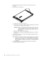
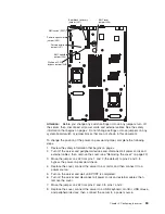
a.
Press
down
and
out
on
the
release
lever
on
the
microprocessor
socket.
Lift
up
the
release
lever
until
it
stops
in
the
fully-open
position
(approximately
135°
angle)
and
the
top
edge
of
the
release
lever
has
moved
away
from
the
microprocessor
socket.
Microprocessor socket
Microprocessor
release lever
Microprocessor
bracket frame
Microprocessor
dust cover
b.
Lift
the
hinged
microprocessor
bracket
frame
into
the
open
position.
Remove
the
protective
cover
from
the
bracket
frame.
Store
the
dust
cover
in
a
safe
place.
7.
Install
the
microprocessor:
a.
Touch
the
static-protective
package
that
contains
the
new
microprocessor
to
any
unpainted
metal
surface
on
the
outside
of
the
server;
then,
remove
the
microprocessor
from
the
package.
b.
Align
the
microprocessor
with
the
socket,
as
shown
in
the
following
illustration
(note
the
alignment
marks
and
the
position
of
the
notches);
then,
carefully
place
the
microprocessor
on
the
socket
and
close
the
microprocessor
bracket
frame.
Attention:
Do
not
use
excessive
force
when
you
insert
the
microprocessor
into
the
socket.
Note:
The
microprocessor
fits
only
one
way
on
the
socket.
Microprocessor
Microprocessor socket
Microprocessor
release lever
Alignment marks
Chapter
2.
Installing
optional
devices
49
Summary of Contents for x3455 - System - 7984
Page 1: ...System x3455 Types 7984 and 7986 User s Guide...
Page 2: ......
Page 3: ...System x3455 Types 7984 and 7986 User s Guide...
Page 70: ...56 System x3455 Types 7984 and 7986 User s Guide...
Page 111: ......
Page 112: ...Part Number 42D2184 Printed in USA 1P P N 42D2184...


