11.
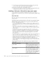
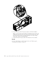
Route the power cable through the cable hook-and-loop on the rear of the
server so that it does not accidentally become unplugged.
12.
Reconnect all of the cables to the peripheral devices.
13.
Restart the server. Make sure that it starts correctly and recognizes the newly
installed device, and make sure that no error LEDs are lit.
Installing a 1400-watt or 900-watt hot-swap power supply
Use this information for installation instructions and notes that you need to
consider when you install 1400-watt or 900-watt ac hot-swap power supplies in the
server.
About this task
Note:
This information and instructions apply to both the 4-socket and the
8-socket servers.
The following notes describe the 1400-watt or 900-watt ac hot-swap power supply
information that you must consider when you install a hot-swap 1400-watt or
900-watt ac hot-swap in the server:
v
If you install additional power supplies or different power supplies, place the
power rating label that comes with the new power supply option on the rear of
the server.
v
Four 900-watt or four 1400-watt hot-swap power supplies fed from a 110 V
input source provides N+N redundancy support for limited configurations (per
4-socket node).
v
Four 1400-watt hot-swap power supplies fed from a 220 V ac input source
provides N+N redundancy support for a full configuration (per 4-socket node).
v
The power supply bays are divided into two power domains. Power supply
bays 1 and 3 are in power domain A and power supply bays 2 and 4 are in
power domain B.
v
To confirm that the server supports the power supply that you are installing, see
http://www.ibm.com/systems/info/x86servers/serverproven/compat/us/.
v
For more notes and information that you must consider when you install power
supplies in the server, see “Installing power supplies” on page 104.
v
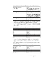
The following table lists the population sequence for the supported power
supply configurations. These configurations apply for each 4-socket node of the
8-socket server.
Table 32. Population sequence for the supported power supply configurations for each
4-socket node
Power supply configuration
Notes:
1 power supply
The power supply should be installed in bay
3. This configuration does not support
power supply redundancy. A power supply
filler must be installed in bays 1, 2, and 4.
2 power supplies
The power supplies should be installed in
bays 2 and 3 with each supply on separate
power feeds for feed redundancy. Both
power supplies must be the same type (that
is, the same wattage, ac power supplies, or
dc power supplies). A power supply filler
must be installed in bays 1 and 4.
110
System x3850 X6 and x3950 X6 Types 3837 and 3839: Installation and Service Guide
Summary of Contents for X3850 X6
Page 1: ...System x3850 X6 and x3950 X6 Types 3837 and 3839 Installation and Service Guide...
Page 2: ......
Page 3: ...System x3850 X6 and x3950 X6 Types 3837 and 3839 Installation and Service Guide...
Page 138: ...120 System x3850 X6 and x3950 X6 Types 3837 and 3839 Installation and Service Guide...
Page 225: ...25 26 27 Chapter 5 Parts listing System x3850 X6 and x3950 X6 Types 3837 and 3839 207...
Page 1682: ...1664 System x3850 X6 and x3950 X6 Types 3837 and 3839 Installation and Service Guide...
Page 1706: ...1688 System x3850 X6 and x3950 X6 Types 3837 and 3839 Installation and Service Guide...
Page 1710: ...1692 System x3850 X6 and x3950 X6 Types 3837 and 3839 Installation and Service Guide...
Page 1728: ...1710 System x3850 X6 and x3950 X6 Types 3837 and 3839 Installation and Service Guide...
Page 1729: ......
Page 1730: ...Part Number 00FH434 Printed in USA 1P P N 00FH434...

