v
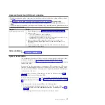
Follow
the
suggested
actions
in
the
order
in
which
they
are
listed
in
the
Action
column
until
the
problem
is
solved.
v
See
to
determine
which
components
are
customer
replaceable
units
(CRU)
and
which
components
are
field
replaceable
units
(FRU).
v
If
an
action
step
is
preceded
by
“(Trained
service
technician
only),”
that
step
must
be
performed
only
by
a
trained
service
technician.
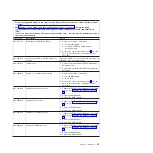
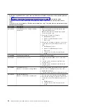
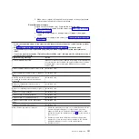
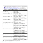
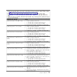
Error
code
Description
Action
405-xxx-00n
Failed
Ethernet
test
on
adapter
in
PCI
slot.
v
For
single
port,
n
>
0
v
For
dual
port,
n
>
1
1.
Complete
the
following
steps
to
identify
the
slot
on
the
riser
card:
a.
Run
the
Configuration/Setup
Utility
program.
b.
Select
Advanced
Setup
-->
PCI
Slot/Device
Information
.
In
the
information
for
Ethernet
Controller,
the
entry
in
the
Slot
column
is
the
PCI
slot
number
for
the
adapter.
Note:
If
adapters
are
installed
in
both
slots
on
the
riser
card,
the
failing
adapter
is
the
one
whose
MAC
address
in
the
Ethernet
controller
information
matches
the
MAC
address
on
the
diagnostics
screen
where
the
failure
occurs.
2.
Reseat
the
Ethernet
adapter
in
the
slot.
3.
Replace
the
Ethernet
adapter
in
the
slot.
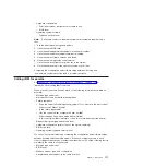
Updating
BIOS
code
The
BIOS
code
can
be
updated
by
using
an
external
USB
diskette
drive
or
by
using
a
Linux
or
Windows
®
update
package
(if
available).
The
most
current
level
of
BIOS
code
for
the
server
is
available
at
After
you
make
sure
that
the
server
has
the
latest
level
of
baseboard
management
controller
firmware,
you
can
update
the
BIOS
code
for
the
server
through
one
of
the
following
methods:
v
Downloading
the
latest
BIOS
code
from
the
IBM
Web
site,
creating
an
update
diskette,
and
using
an
external
USB
diskette
drive
to
install
the
BIOS
code.
v
Installing
an
update
package
for
the
Linux
or
Microsoft
®
Windows
operating
system,
if
available.
If
power
to
the
server
is
interrupted
while
the
POST/BIOS
code
is
being
updated
(flash
update),
the
server
might
not
restart
correctly
or
might
not
display
video
(no
video).
If
this
happens,
use
the
following
procedure
to
recover:
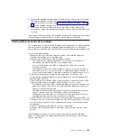
1.
Read
the
safety
information
that
begins
on
page
and
2.
Turn
off
the
server
and
peripheral
devices
and
disconnect
all
external
cables
and
power
cords;
remove
the
server
from
the
rack
and
place
it
on
a
flat,
static-protective
surface;
then,
remove
the
cover.
3.
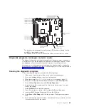
Locate
the
boot
block
recovery
jumper
(JP4
on
the
system
board)
(see
4.
Move
the
boot
block
recovery
jumper
from
pins
1
and
2
to
pins
2
and
3.
5.
Replace
the
server
cover.
6.
Connect
the
server
to
the
power
source,
keyboard,
monitor,
and
mouse.
Chapter
5.
Diagnostics
99
Summary of Contents for xSeries 206m
Page 1: ...IBM xSeries 306m Types 8849 and 8491 Problem Determination and Service Guide...
Page 2: ......
Page 3: ...IBM xSeries 306m Types 8849 and 8491 Problem Determination and Service Guide...
Page 8: ...vi IBM xSeries 306m Types 8849 and 8491 Problem Determination and Service Guide...
Page 143: ......
Page 144: ...Part Number 31R1183 Printed in USA 1P P N 31R1183...


