


Diagnostic
programs,
error
codes
and
messages
The
server
diagnostic
programs
are
stored
in
electrically
erasable
programmable
read-only
memory
(EEPROM)
on
the
system
board
that
is
shared
with
the
BIOS
code.
These
programs
are
the
primary
method
of
testing
the
major
components
of
your
server.
Diagnostic
error
messages
indicate
that
a
problem
exists.
They
are
not
intended
to
be
used
to
identify
a
failing
part.
Troubleshooting
and
servicing
of
complex
problems
that
are
indicated
by
error
messages
should
be
performed
by
trained
service
personnel.
Sometimes
the
first
error
to
occur
causes
additional
errors.
In
this
case,
the
server
displays
more
than
one
error
message.
Always
follow
the
suggested
action
instructions
for
the
first
error
message
that
appears.
Error
codes
that
might
be
displayed
are
listed
at
“Diagnostic
error
codes”
on
page
116.
Notes:
1.
Depending
on
the
server
configuration,
some
of
the
error
codes
might
not
appear
when
you
run
the
diagnostic
programs.
2.
If
diagnostic
error
codes
appear
that
are
not
listed
in
the
tables,
make
sure
that
the
server
has
the
latest
levels
of
BIOS,
Remote
Supervisor
Adapter
II
SlimLine,
and
ServeRAID
code
installed.
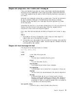
Diagnostic
text
message
format
The
diagnostic
text
message
format
is
as
follows:
result
test_specific_string
where:
result
is
one
of
the
following
results:
Passed
This
test
was
completed
without
any
errors.
Failed
This
test
discovered
an
error.
User
Aborted
You
stopped
the
test
before
it
was
completed.
Not
Applicable
You
attempted
to
test
a
device
that
is
not
present
in
the
server.
Aborted
The
test
could
not
proceed
because
of
the
server
configuration.
Warning
A
hardware
failure
did
not
occur;
the
test
could
not
be
run
because
of
some
other
problem
(for
example,
there
might
be
a
configuration
problem,
the
hardware
is
missing
or
is
not
being
recognized,
or
there
is
a
hardware
problem
that
is
not
related
to
the
hardware
currently
being
tested).
test_specific_string
is
an
error
code
or
other
information
about
the
error.
Chapter
5.
Diagnostics
91
Summary of Contents for xSeries 236 8841
Page 1: ...xSeries 236 Type 8841 Hardware Maintenance Manual and Troubleshooting Guide...
Page 2: ......
Page 3: ...xSeries 236 Type 8841 Hardware Maintenance Manual and Troubleshooting Guide...
Page 20: ...10 xSeries 236 Type 8841 Hardware Maintenance Manual and Troubleshooting Guide...
Page 96: ...86 xSeries 236 Type 8841 Hardware Maintenance Manual and Troubleshooting Guide...
Page 152: ...142 xSeries 236 Type 8841 Hardware Maintenance Manual and Troubleshooting Guide...
Page 160: ...150 xSeries 236 Type 8841 Hardware Maintenance Manual and Troubleshooting Guide...
Page 173: ...Appendix B Safety information 163...
Page 174: ...164 xSeries 236 Type 8841 Hardware Maintenance Manual and Troubleshooting Guide...
Page 175: ...Appendix B Safety information 165...
Page 176: ...166 xSeries 236 Type 8841 Hardware Maintenance Manual and Troubleshooting Guide...
Page 177: ...Appendix B Safety information 167...
Page 178: ...168 xSeries 236 Type 8841 Hardware Maintenance Manual and Troubleshooting Guide...
Page 179: ...Appendix B Safety information 169...
Page 189: ...Appendix B Safety information 179...
Page 190: ...180 xSeries 236 Type 8841 Hardware Maintenance Manual and Troubleshooting Guide...
Page 191: ...Appendix B Safety information 181...
Page 192: ...182 xSeries 236 Type 8841 Hardware Maintenance Manual and Troubleshooting Guide...
Page 196: ...186 xSeries 236 Type 8841 Hardware Maintenance Manual and Troubleshooting Guide...
Page 208: ...198 xSeries 236 Type 8841 Hardware Maintenance Manual and Troubleshooting Guide...
Page 209: ......
Page 210: ...Part Number 25K8114 1P P N 25K8114...


