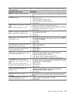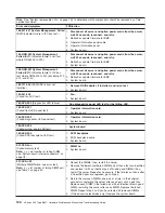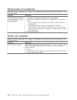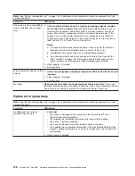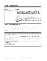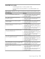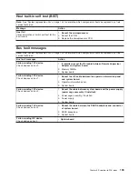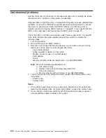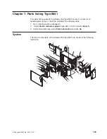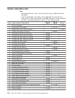
Note:
See
“System
replaceable
units”
on
page
144
to
determine
which
components
should
be
replaced
by
a
field
service
technician.
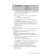
Symptom
FRU/action
An
IBM
option
that
used
to
work
does
not
work
now.
1.
Verify
that
all
of
the
option
hardware
and
cable
connections
are
secure.
2.
If
the
option
comes
with
its
own
test
instructions,
use
those
instructions
to
test
the
option.
3.
If
the
failing
option
is
a
SCSI
option,
verify
that:
v
The
cables
for
all
external
SCSI
options
are
connected
correctly.
v
The
last
option
in
each
SCSI
chain,
or
the
end
of
the
SCSI
cable,
is
terminated
correctly.
v
Any
external
SCSI
option
is
turned
on.
You
must
turn
on
an
external
SCSI
option
before
turning
on
the
server.
4.
Failing
option.
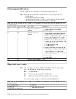
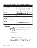
Power
error
symptoms
Note:
See
“System
replaceable
units”
on
page
144
to
determine
which
components
should
be
replaced
by
a
field
service
technician.
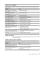
Symptom
FRU/action
The
power
switch
does
not
work
and
the
reset
button,
if
supported,
does
work.
1.
Reseat
the
connector.
2.
Power
switch
card.
3.
System
board.
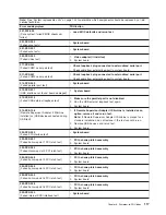
The
server
does
not
turn
on.
1.
Verify
that:
v
The
power
cables
are
properly
connected
to
the
server.
v
The
power
supply
LEDs
indicate
correct
operation
(see
“Power-supply
LED
errors”
on
page
116).
v
The
electrical
outlet
functions
properly.
v
The
type
of
memory
installed
is
supported
by
the
server,
and
that
functional
DIMMs
are
installed
in
slots
1
and
2.
v
If
you
just
installed
an
option,
remove
it,
and
restart
the
server.
If
the
server
now
turns
on,
you
might
have
installed
more
options
than
the
power
supply
supports.
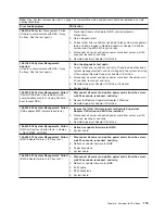
2.
If
LEDs
for
microprocessors
or
VRMs
are
on,
verify
that:
a.
A
VRM
is
installed
if
a
second
microprocessor
is
present.
b.
All
microprocessors
have
the
same
speed.
3.
Override
front
panel
power
button:
a.
Disconnect
server
power
cords.
b.
Move
the
force
power-on
password
switch
(SW1)
from
its
upward
position
to
its
lower
position.
c.
Reconnect
power
cords.
If
server
turns
on:
a.
Service
processor
(baseboard
management
controller)
error.
b.
Operator
information
card.
If
server
does
not
turn
on:
v
System
board
Chapter
6.
Symptom-to-FRU
index
129
Summary of Contents for xSeries 236 8841
Page 1: ...xSeries 236 Type 8841 Hardware Maintenance Manual and Troubleshooting Guide...
Page 2: ......
Page 3: ...xSeries 236 Type 8841 Hardware Maintenance Manual and Troubleshooting Guide...
Page 20: ...10 xSeries 236 Type 8841 Hardware Maintenance Manual and Troubleshooting Guide...
Page 96: ...86 xSeries 236 Type 8841 Hardware Maintenance Manual and Troubleshooting Guide...
Page 152: ...142 xSeries 236 Type 8841 Hardware Maintenance Manual and Troubleshooting Guide...
Page 160: ...150 xSeries 236 Type 8841 Hardware Maintenance Manual and Troubleshooting Guide...
Page 173: ...Appendix B Safety information 163...
Page 174: ...164 xSeries 236 Type 8841 Hardware Maintenance Manual and Troubleshooting Guide...
Page 175: ...Appendix B Safety information 165...
Page 176: ...166 xSeries 236 Type 8841 Hardware Maintenance Manual and Troubleshooting Guide...
Page 177: ...Appendix B Safety information 167...
Page 178: ...168 xSeries 236 Type 8841 Hardware Maintenance Manual and Troubleshooting Guide...
Page 179: ...Appendix B Safety information 169...
Page 189: ...Appendix B Safety information 179...
Page 190: ...180 xSeries 236 Type 8841 Hardware Maintenance Manual and Troubleshooting Guide...
Page 191: ...Appendix B Safety information 181...
Page 192: ...182 xSeries 236 Type 8841 Hardware Maintenance Manual and Troubleshooting Guide...
Page 196: ...186 xSeries 236 Type 8841 Hardware Maintenance Manual and Troubleshooting Guide...
Page 208: ...198 xSeries 236 Type 8841 Hardware Maintenance Manual and Troubleshooting Guide...
Page 209: ......
Page 210: ...Part Number 25K8114 1P P N 25K8114...

