


v
Each DIMM in a pair must be of the same size and technology to ensure that the
server will operate properly.
v
You can configure your server to use memory mirroring and memory scrubbing.
For detailed information about configuring your server and using these features,
see the
User’s Guide
on the IBM
xSeries Documentation
CD.
v
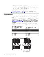
When using memory mirroring, you must install two pairs of DIMMs at a time.
The four DIMMs in each bank must be identical. The following table shows the
pairs that are in each bank. See Table 2 on page 26 for the DIMM connector pair
assignments.
Table 3. Memory mirroring DIMM installation sequence
Bank
DIMM pairs
Bank
DIMM pairs
1
1 and 2
5
9 and 10
2
3 and 4
6
11 and 12
3
5 and 6
7
13 and 14
4
7 and 8
v
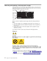
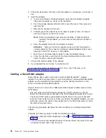
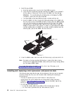
You can replace a failed DIMM while the server is on, provided that you have
enabled memory mirroring and that you have installed all DIMMs in the sequence
to support memory mirroring.
If a problem with a DIMM is detected, light path diagnostics will light the
system-error LED on the front of the server, indicating that there is a problem
and guide you to the defective DIMM. When this occurs, first identify the
defective DIMM; then, remove and replace the DIMM. See “Hot-replacing
DIMMs” on page 29 for instructions.
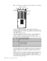
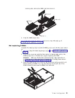
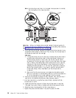
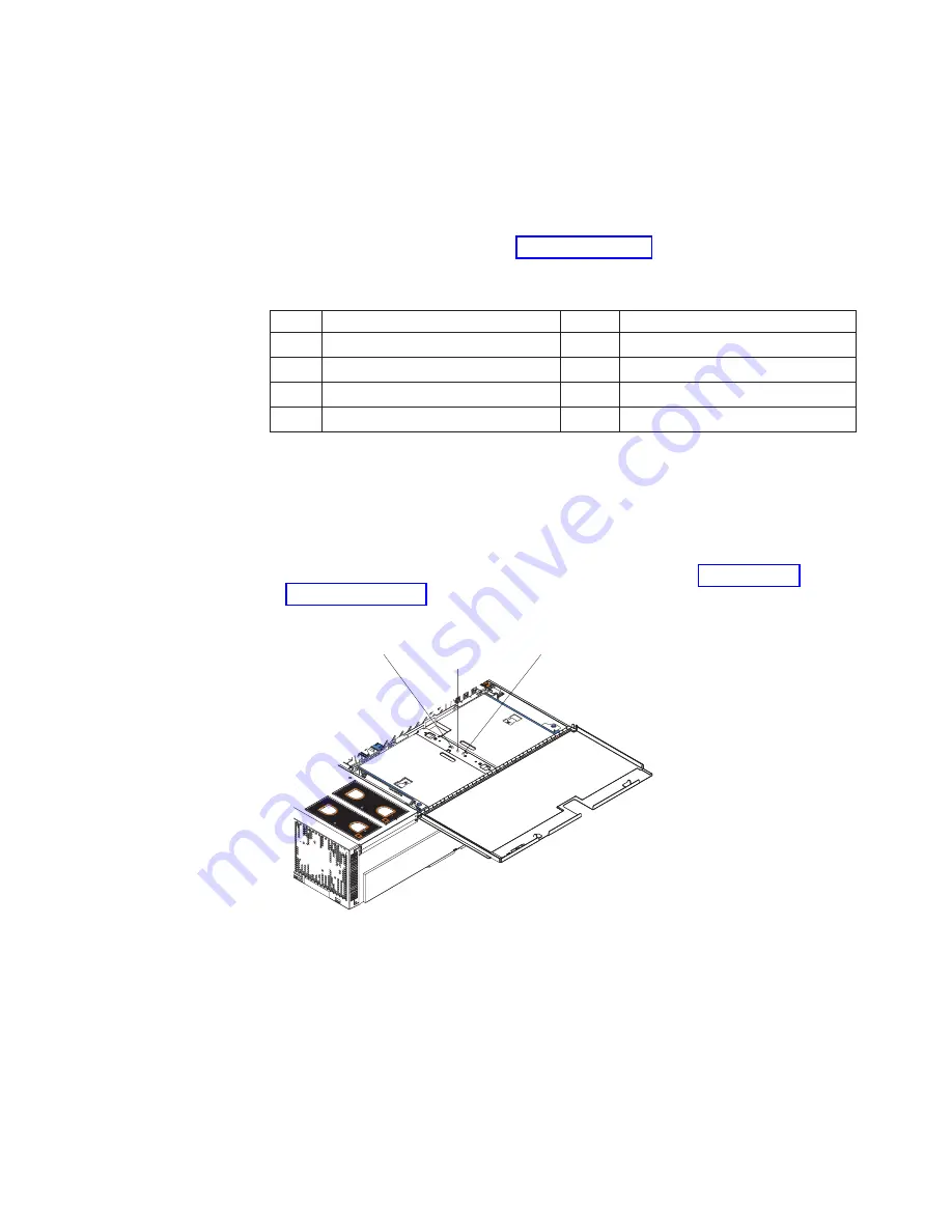
The following illustration shows the LEDs on the DIMM access door:
Port 1 power LED
Port 2 power LED
Memory hot-plug
enabled LED
NO
TE
:
FO
R P
RO
PE
R A
IR
FLO
W,
R
EP
LA
CE
FA
N
W
IT
HIN
2 M
IN
UT
ES
FR
ON
T O
F B
OX
NO
TE
:
FO
R P
RO
PE
R A
IR
FLO
W,
R
EP
LA
CE
FA
N
W
IT
HIN
2 M
IN
UT
ES
FR
ON
T O
F B
OX
Port 1 power LED:
When this LED is off, it indicates that power is removed from
the port and that you can replace a failed DIMM.
Memory hot-plug enabled LED:
When this LED is lit, it indicates that hot-swap
memory is enabled. When this LED is flashing, it indicates that data is being
mirrored on the replacement DIMMs.
Port 2 power LED:
When this LED is off, it indicates that power is removed from
the port and that you can replace a failed DIMM.
Chapter 2. Installing options
27
Summary of Contents for xSeries 455
Page 1: ...xSeries 455 Option Installation Guide ERserver...
Page 2: ......
Page 3: ...xSeries 455 Option Installation Guide SC88 P919 80 ERserver...
Page 12: ...x xSeries 455 Option Installation Guide...
Page 24: ...12 xSeries 455 Option Installation Guide...
Page 70: ...58 xSeries 455 Option Installation Guide...
Page 74: ...62 xSeries 455 Option Installation Guide...
Page 82: ...70 xSeries 455 Option Installation Guide...
Page 85: ......
Page 86: ...Part Number 88P9198 Printed in U S A SC88 P919 80 1P P N 88P9198...


