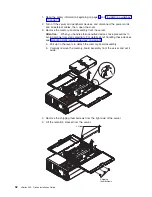
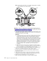


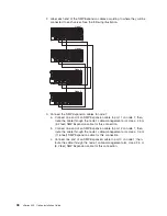

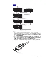


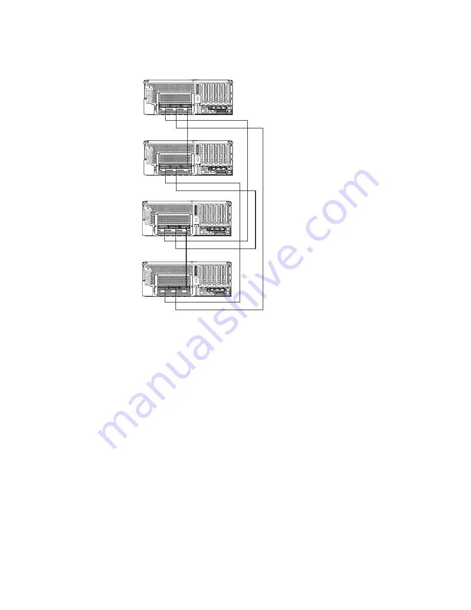
2. Label each end of the SMP Expansion cables according to where they will be
connected to each server. See the following illustration.
1
2
3
Node 1
1
2
3
Node 2
1
2
3
Node 3
1
2
3
Node 4
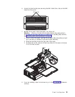
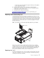
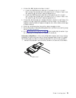
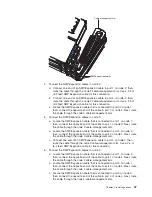
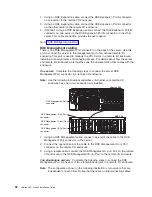
3. Connect the SMP Expansion cables to node 1:
a. Connect one end of an SMP Expansion cable to port 1 on node 1; then,
route the cable through the node 1 cable-management arm. Use a 2.5 m
(8.2 feet) SMP Expansion cable for this connection.
b. Connect one end of an SMP Expansion cable to port 2 on node 1; then,
route the cable through the node 1 cable-management arm. Use a 3.5 m
(11.6 feet) SMP Expansion cable for this connection.
c. Connect one end of an SMP Expansion cable to port 3 on node 1; then,
route the cable through the node 1 cable-management arm. Use a 2.5 m
(8.2 feet) SMP Expansion cable for this connection.
46
xSeries 455: Option Installation Guide
Summary of Contents for xSeries 455
Page 1: ...xSeries 455 Option Installation Guide ERserver...
Page 2: ......
Page 3: ...xSeries 455 Option Installation Guide SC88 P919 80 ERserver...
Page 12: ...x xSeries 455 Option Installation Guide...
Page 24: ...12 xSeries 455 Option Installation Guide...
Page 70: ...58 xSeries 455 Option Installation Guide...
Page 74: ...62 xSeries 455 Option Installation Guide...
Page 82: ...70 xSeries 455 Option Installation Guide...
Page 85: ......
Page 86: ...Part Number 88P9198 Printed in U S A SC88 P919 80 1P P N 88P9198...


