

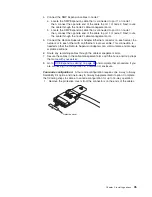

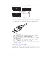


3. Connect the opposite end of the cable to an RXE Expansion Port connector on
the remote I/O enclosure.
Go to “RXE Management cabling” on page 52.
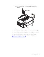
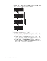
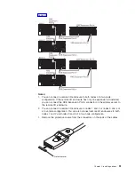
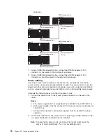
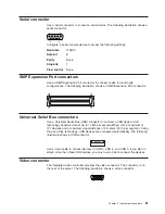
Complete the following steps to connect the server to a remote I/O enclosure with
two expansion kits installed.
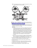
RXE-100
RXE Expansion
Port A
connector
RXE Expansion Port B
connector
RXE Expansion Port connectors
xSeries 455
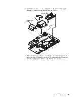
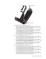
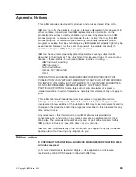
1. Remove the protective covers from the connectors on the ends of the cables.
Protective cover
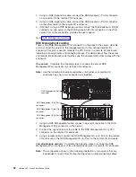
2. Using an RXE Expansion cable, connect one end of the cable to the RXE
Expansion Port A connector on the server.
3. Connect the opposite end of the cable to an RXE Expansion Port connector on
the remote I/O enclosure.
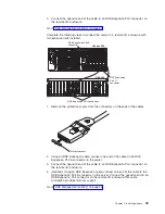
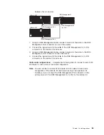
4. (Optional) Using an RXE Expansion cable, connect one end of the cable to the
RXE Expansion Port B connector on the server. Connect the opposite end to an
RXE Expansion Port connector on the remote I/O enclosure.This cable
connection provides fail-over support.
Go to “RXE Management cabling” on page 52.
Chapter 2. Installing options
49
Summary of Contents for xSeries 455
Page 1: ...xSeries 455 Option Installation Guide ERserver...
Page 2: ......
Page 3: ...xSeries 455 Option Installation Guide SC88 P919 80 ERserver...
Page 12: ...x xSeries 455 Option Installation Guide...
Page 24: ...12 xSeries 455 Option Installation Guide...
Page 70: ...58 xSeries 455 Option Installation Guide...
Page 74: ...62 xSeries 455 Option Installation Guide...
Page 82: ...70 xSeries 455 Option Installation Guide...
Page 85: ......
Page 86: ...Part Number 88P9198 Printed in U S A SC88 P919 80 1P P N 88P9198...


