


Chapter 3. Input/output connectors
Your server has the following input/output connectors:
v
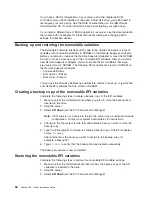
Two Gigabit Ethernet (RJ-45)
v
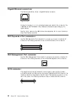
Two RXE Expansion Port
v
One RXE Management Port
v
One SCSI
v
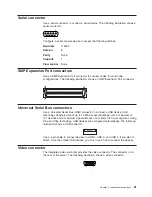
One serial
v
Three SMP Expansion Port
v
Three Universal Serial Bus (USB)
v
One video
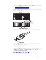
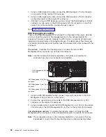
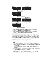
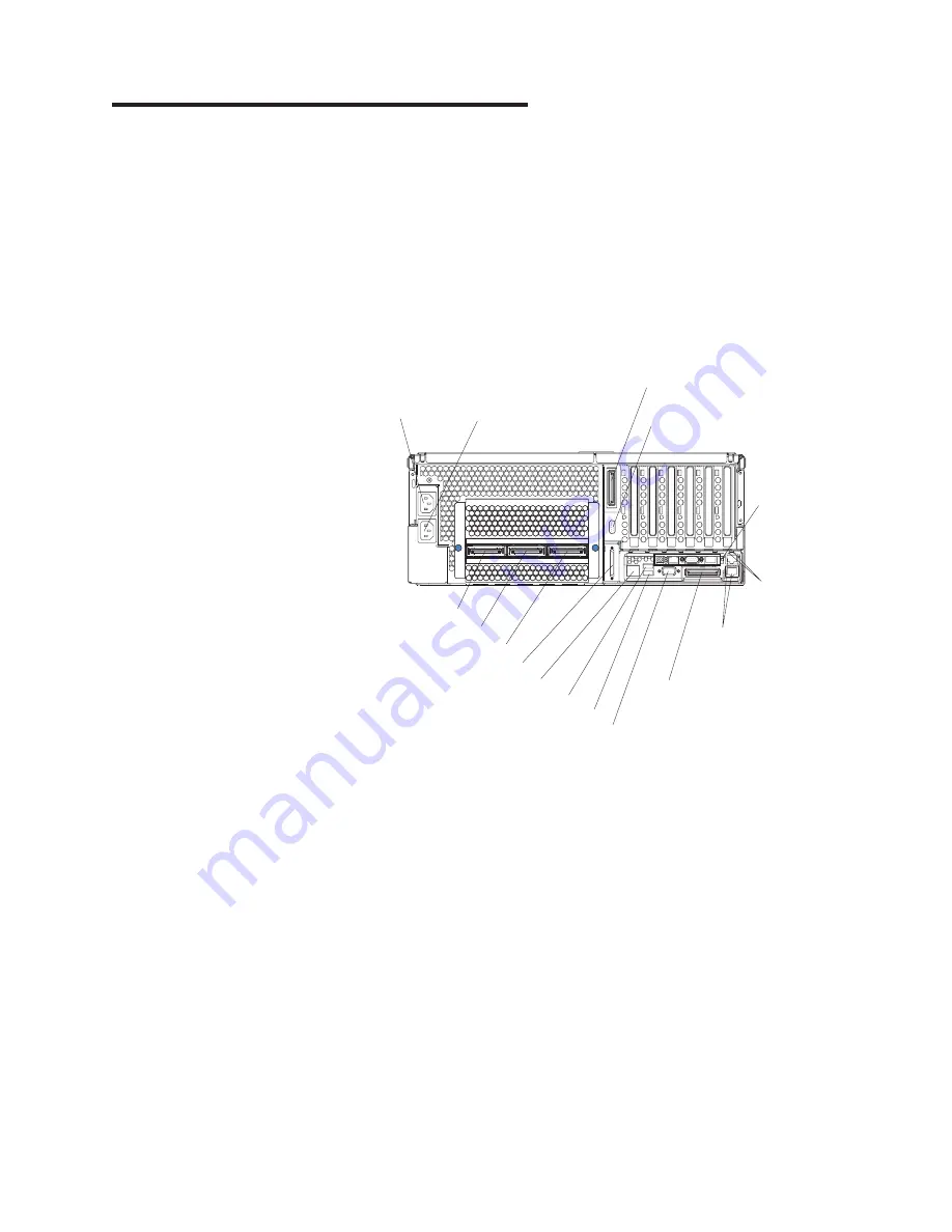
The following illustration shows the locations of these connectors.
System power
connector (1)
System power
connector (2)
RXE Expansion Port (B)
connector
Remote
Supervisor
Adapter
connectors
and LEDs
Ethernet
LEDs
Gigabit Ethernet
connectors
RXE Expansion
Port (A) connector
Video connector
USB 2 connector
USB 1 connector
RXE Management Port connector
SCSI connector
Serial connector
SMP Expansion Port 1 connector
SMP Expansion Port 2 connector
SMP Expansion Port 3 connector
The following sections describe these connectors.
Your server also has an additional Ethernet connector, an additional serial
connector, and an Advanced System Management (ASM) Interconnect connector on
the Remote Supervisor Adapter. See the Remote Supervisor Adapter documentation
on the IBM
xSeries Documentation
CD for more information.
© Copyright IBM Corp. 2003
59
Summary of Contents for xSeries 455
Page 1: ...xSeries 455 Option Installation Guide ERserver...
Page 2: ......
Page 3: ...xSeries 455 Option Installation Guide SC88 P919 80 ERserver...
Page 12: ...x xSeries 455 Option Installation Guide...
Page 24: ...12 xSeries 455 Option Installation Guide...
Page 70: ...58 xSeries 455 Option Installation Guide...
Page 74: ...62 xSeries 455 Option Installation Guide...
Page 82: ...70 xSeries 455 Option Installation Guide...
Page 85: ......
Page 86: ...Part Number 88P9198 Printed in U S A SC88 P919 80 1P P N 88P9198...


