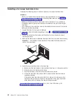


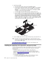
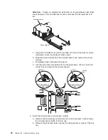
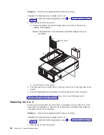


4. Install the new DIMM:
a. Open the retaining clip on each end of the DIMM connector.
b. Touch the static-protective package containing the DIMM to any unpainted
metal surface on the server. Then, remove the DIMM from the package.
Attention:
To avoid breaking the retaining clips or damaging the DIMM
connectors, open and close the clips gently.
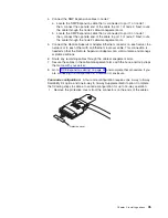
c. Turn the DIMM so that the DIMM keys align correctly with the slot.
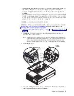
d. Insert the DIMM into the connector by aligning the edges of the DIMM with
the slots at the ends of the DIMM connector. Firmly press the DIMM straight
down into the connector by applying pressure on both ends of the DIMM
simultaneously. The retaining clips snap into the locked position when the
DIMM is firmly seated in the connector. If there is a gap between the DIMM
and the retaining clips, the DIMM has not been correctly inserted; open the
retaining clips, remove the DIMM, and then reinsert it.
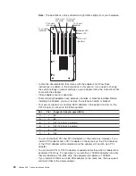
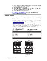
DIMM slot 15
DIMM slot 1
DIMM slot 28
DIMM slot 14
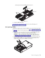
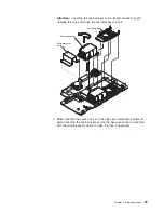
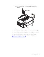
5. Close the DIMM access door and verify that the memory port power LED is lit.
Note:
The memory hot-plug enabled LED flashes to indicate that data is being
mirrored on the replacement DIMMs. Wait until the LED stops flashing before
you hot-replace DIMMs again.
If you have other options to install or remove, do so now. Otherwise, go to
“Completing the installation” on page 41.
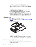
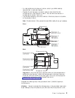
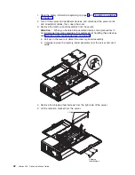
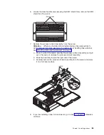
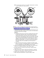
Installing and replacing a microprocessor and power module
The following notes describe the type of microprocessor that your server supports
and other information that you must consider when installing and replacing a
microprocessor:
v
Your server supports up to four Intel
®
Itanium 2 microprocessors.
v
Update the server system abstraction layer/extensible firmware interface
(SAL/EFI) code. To download the most current level of SAL/EFI code for the
server, go to http://www.ibm.com/pc/support/.
v
You will need the following tools:
– 2.5-mm hex (Allen) wrench (provided with the microprocessor option)
– T15 Torx wrench (provided with the microprocessor option)
30
xSeries 455: Option Installation Guide
Summary of Contents for xSeries 455
Page 1: ...xSeries 455 Option Installation Guide ERserver...
Page 2: ......
Page 3: ...xSeries 455 Option Installation Guide SC88 P919 80 ERserver...
Page 12: ...x xSeries 455 Option Installation Guide...
Page 24: ...12 xSeries 455 Option Installation Guide...
Page 70: ...58 xSeries 455 Option Installation Guide...
Page 74: ...62 xSeries 455 Option Installation Guide...
Page 82: ...70 xSeries 455 Option Installation Guide...
Page 85: ......
Page 86: ...Part Number 88P9198 Printed in U S A SC88 P919 80 1P P N 88P9198...


